The Engineer’s Manual
of Construction Site
Planning

The Engineer’s Manual
of Construction Site
Planning
Jüri Sutt
Professor of Construction Economics and Management
Tallinn University of Technology
Irene Lill
Professor and Head of Department of Building Production
Tallinn University of Technology
Olev Müürsepp
Associated Professor
Tallinn University of Technology
This edition first published 2013
© 2013 John Wiley & Sons, Ltd
Registered Office
John Wiley & Sons, Ltd, The Atrium, Southern Gate, Chichester, West Sussex, PO19 8SQ,
United Kingdom
Editorial Offices
9600 Garsington Road, Oxford, OX4 2DQ, United Kingdom.
The Atrium, Southern Gate, Chichester, West Sussex, PO19 8SQ, United Kingdom.
For details of our global editorial offices, for customer services and for information about how
to apply for permission to reuse the copyright material in this book please see our website at
www.wiley.com/wiley-blackwell.
The right of the author to be identified as the author of this work has been asserted in
accordance with the UK Copyright, Designs and Patents Act 1988.
All rights reserved. No part of this publication may be reproduced, stored in a retrieval system,
or transmitted, in any form or by any means, electronic, mechanical, photocopying, recording
or otherwise, except as permitted by the UK Copyright, Designs and Patents Act 1988,
without the prior permission of the publisher.
Designations used by companies to distinguish their products are often claimed as trademarks.
All brand names and product names used in this book are trade names, service marks,
trademarks or registered trademarks of their respective owners. The publisher is not
associated with any product or vendor mentioned in this book.
Limit of Liability/Disclaimer of Warranty: While the publisher and author(s) have used their
best efforts in preparing this book, they make no representations or warranties with respect to
the accuracy or completeness of the contents of this book and specifically disclaim any implied
warranties of merchantability or fitness for a particular purpose. It is sold on the understanding
that the publisher is not engaged in rendering professional services and neither the publisher
nor the author shall be liable for damages arising herefrom. If professional advice or other
expert assistance is required, the services of a competent professional should be sought.
Library of Congress Cataloging-in-Publication Data
Sutt, Jüri.
The engineer’s manual of construction site planning / Jüri Sutt, Irene Lill, Olev Müürsepp.
pages cm
Includes index.
ISBN 978-1-118-55609-2 (pbk.)
1. Building sites–Planning–Handbooks, manuals, etc. 2. Building–Superintendence–
Handbooks, manuals, etc. 3. Civil engineering–Handbooks, manuals, etc. I. Lill, Irene.
II. Müürsepp, Olev, 1936– III. Title. IV. Title: Manual of construction site planning.
TH375.S88 2013
692′.1–dc23
2013002862
A catalogue record for this book is available from the British Library.
Wiley also publishes its books in a variety of electronic formats. Some content that appears in
print may not be available in electronic books.
Cover image: © iStockphoto/urbanglimpses
Cover design by Meaden Creative
Set in 11/14pt Palatino by SPi Publisher Services, Pondicherry, India
1 2013
v
Contents
List of Figures viii
List of Tables x
About the Authors xi
Preface xiii
Introduction 1
Chapter 1: Initial data 5
1.1 The project (design) documentation 6
1.2 The bill of quantities and the bill of activities 7
1.3 Job descriptions and specifications 7
1.4 The contract conditions set out in the bidding
invitation documents 8
1.5 The report of the construction site inspection 8
Chapter 2: Outline of site management
planning in the bidding stage 15
2.1 The goal 16
2.2 The explanatory note 16
2.3 Construction site layout 19
2.4 The construction time schedule 21
2.5 Cost estimation of temporary works
and construction site set-up 23
Chapter 3: Outline of site management
after contract signature 28
3.1 The goal 29
3.2 Initial data 29
3.3 Construction site layout 30
3.4 Construction scheduling 35
3.5 Calculation of site work quantities and
estimate of costs 46

vi Contents
Chapter 4: Suggestions for choosing
constructioncranes 51
4.1 General 52
4.2 Selection and positioning of tower cranes 53
4.3 Selection and impact areas of mobile cranes 77
4.4 Cranes working near overhead power lines 91
4.5 Hoist danger area 94
4.6 Operating cranes near buildings in use 95
4.7 Restrictions on crane work 97
4.8 Working in the danger area 98
Chapter 5: Suggestions for calculating
resource requirements 99
5.1 Construction site temporary roads 100
5.2 Construction site storage 105
5.3 Temporary buildings 111
5.4 Temporary water supply 115
5.5 Temporary heating supply 116
5.6 Temporary power supply 121
5.7 Construction site lighting 126
5.8 Construction site transport 127
5.9 Load take up devices 130
5.10 Construction site fencing 135
Chapter 6: On-site safety requirements 137
6.1 General basics and responsibilities 138
6.2 The duties of building contractors 141
6.3 The obligations and rights of the labourer 144
6.4 Ensuring safety on the construction site 146
Chapter 7: Requirements for work equipment 155
7.1 General requirements 156
7.2 Mobile work equipment 158
7.3 Lifting devices 160
7.4 Dangers from energy 161
7.5 The usage of work equipment 163

Contents vii
7.6 Usage of work equipment for temporary
work at height 164
7.7 Work with flammable and explosive materials 168
Chapter 8: Work healthcare 169
8.1 Allowable physical effort 170
8.2 The usage of personal protective equipment 170
8.3 Welfare facilities and first-aid 171
Appendix: Construction site layout symbols 173
Bibliography 177
Index 178
viii
List of Figures
Figure2.1 Site layout in the bidding stage 20
Figure2.2 An example of a time schedule in the
bidding stage 22
Figure3.1 An example of construction site layout for
the frame erection stage 34
Figure3.2 Network model for construction 37
Figure4.1 Drafting geometrical parameters for
a tower crane 54
Figure4.2 Tower crane Liebherr 550 EC-H40 Litronic
radius and capacity chart 57
Figure4.3 Cross-linking the tower crane to the axes
of the building under construction 59
Figure4.4 Positioning the crane track on the edge
of an unsupported recess slope 60
Figure4.5 Longitudinal linking of the tower crane
with building under construction 63
Figure4.6 Danger areas around the building 66
Figure4.7 Boundaries of the danger area 66
Figure4.8 The tower crane impact areas 69
Figure4.9 Danger areas above the building 70
Figure4.10 Simultaneous operation of two cranes
on the same rail track 73
Figure4.11 Simultaneous operation of two cranes
positioned on opposite sides of the building 75
Figure4.12 Simultaneous work of two cranes positioned
between two buildings under construction 76
Figure4.13 Calculating mobile crane minimum
boom length 78
Figure4.14 Assembling at an angle 81

List of Figures ix
Figure4.15 Example of determining the assembly
parameters based on lifting capacity chart
for the RDK 25 crawler crane 85
Figure4.16 Example of determining the assembly
parameters for the Liebherr LTM 1030
mobile crane 86
Figure4.17 Positioning of mobile cranes at the edge of
unsupported recess slopes 88
Figure4.18 The minimal acceptable horizontal
distance s
5
from the bottom edge of a recess
with an unsupported slope to the nearest
outrigger of the crane (m) 89
Figure4.19 Danger area of mobile crane equipped
with boom fall prevention device 90
Figure4.20 Surveillance and danger areas of aerial
power lines 91
Figure4.21 Extent of the surveillance and danger area
of the electrical overhead power line 92
Figure4.22 Safe positioning of mobile crane close
to overhead power lines 94
Figure4.23 Conditions of operation for tower crane
near a building in service 96
Figure5.1 Various kinds of construction site road 104
Figure5.2 Double- and quadruple-branched slings 132
x
List of Tables
Table2.1 Example form of construction site cost
estimate during the bidding stage 26
Table3.1 Example of construction work classication 44
Table3.2 List of costs for temporary and building site
management works 47
Table4.1 Assembly parameters of precast elements
andlifting parameters of tower crane 56
Table4.2 Assembly parameters of precast elements 82
Table4.3 Lifting parameters of chosen mobile cranes
compared to the assembly parameters
of precast elements 84
Table5.1 Average space required for storage of
construction materials 110
Table5.2 Recommendations for surface lighting
in construction 125
xi
About the Authors
Jüri Sutt has nearly 50 years of experience in construction
management as a practicing manager, researcher, consultant
and lecturer which has included designing the construction
technology for large mines in Siberia, a gas trunk pipeline
in Libya and managing a construction firm. In 1965, he
pioneered the use of IT in construction management research
in Estonia. Between 1965 and 1980, J. Sutt was a member of
several USSR scientific councils in the field of construction
management, and from 1965 to 1978, he was the head of the
Construction Management Department of Estonia’s State
Building Research Institute which developed scheduling and
cost estimating IT systems that were widely used in the
Soviet Union.
He has been an adviser to four ministers responsible for building
during Estonia’s transition to a free market economy and led
working groups elaborating construction market regulations in
the 1990s. In addition, he has provided consultancy services for
clients’ projects and contract management and has gained
expertise in contract disputes in the last 15 years.
In 1960, J. Sutt qualified as a construction engineer. He was
awarded the Candidate of Science degree in 1968 (equivalent
to a PhD), and, in 1989, the Doctor of Science (habil.) in math-
ematical methods and IT in economics. The principal outcome
of his research has been the methodology of IT simulating
production – economic activities of construction firms enabling
experimentation with different economic mechanisms and
management strategies in construction enterprises.

Since 1989, he has been Professor of Construction Economics
and Management at the Tallinn University of Technology.
Irene Lill graduated from Tallinn University of Technology as
civil engineer, and defended her degrees in the same univer-
sity (PhD and MSc in Economics). She has over 20 years of
academic experience in the university. She has been working
in research closely with Jüri Sutt, initially as professor and
student and as good colleagues today. Since 2005, she has been
professor and head of department of Building Production in
Tallinn University of Technology.
Olev Müürsepp graduated from Tallinn University of Tech-
nology as a civil engineer. He has nearly ten years of experience
working as a site and project manager in a construction enter-
prise and three years in a large design firm as a consulting
engineer in the field of design of technology and organisation
of construction. For 10 years, he has worked in the Construction
Management Department of Estonia’s State Building Research
Institute as a researcher in the field of modelling technologi-
cal and organisational decisions in civil engineering. In 1987,
he defended his PhD in this specialist area of construction
engineering. Since1991, he has worked as associated professor
in Tallinn University of Technology.
xii About the Authors
xiii
Preface
This handbook deals with the problems of engineering prepa-
ration for building in a construction company, both during the
bidding phase and after a contract has been concluded.
The handbook’s recommendations can also be used in the
design phase, when the building contractor is not yet
selected. In this case, it has the aim of assuring the con-
structability of the designed building and of calculating a
control estimate for the owner in order that bids can be
weighted and contractors’ potential duration of construction
can be evaluated. In the design stage, the methods used are
similar to those of the contractor in the bidding phase, when
aggregated norms are used.
The key problems consist of identifying the composition of
complex project organisation and level of detail of the initial
data, the inspection of the construction site, compiling the
construction site layout and the construction schedule, and
the cost estimate of construction site expenses. Suggestions
for calculating the resource allocation are presented: for
the selection of cranes and lifting devices, the planning
of temporary buildings and roads, and for technological
networks, fire safety, fencing and lighting. On-site safety
precautions in planning of the construction site management
are discussed.
The owner’s construction costs are determined through
cooperation between the owner and the designer/consultant,
according to preliminary design task as set out by the

xiv Preface
ownerand the designer’s technical and aesthetic competence.
Thestructural designer must ensure the building’s strength,
stability, compliance with environmental criteria, etc. These
costs are also affected by the detailed plan requirements
validated by the local authorities. Another concern is
thatnot enough attention is paid to construction management
and building technology during the design of the construc-
tion contract conditions, and their subsequent negotiation.
This, however, impacts the duration of construction, and
based on this the contractor will be able to make the lowest
price offer without reducing the quality of constructing.
Often ignored is the fact that temporary works and
tempo rary facilities on the building site form up to 12% of
total costs, depending on the type of the building, site
conditions, seasonality and the building owner’s stipulations
on duration.
This can be explained by the fact that construction site
management and temporary facilities costs are not reflected
in the final physical form of the building and will therefore
remain unnoticed unless specially outlined by the consultant.
Construction site management is reflected in the economic
result of the owner’s investment in the construction project,
especially for business projects. The quicker the construction is
completed, the sooner it becomes profitable.
For example, for a building that costs €100 million, with an
annual profit rate of 10%, shortening the duration of con-
struction would provide an additional monthly profit of
approximately €0.8 million, and furthermore, it would enable
the saving of about €0.5 million on the construction loan inter-
est payments. Nevertheless, it should not be forgotten that for
the contractor, this may entail organising the work into several
shifts, bearing in mind winter conditions, etc., and the resulting
additional costs will need to be compensated.

Preface xv
For this reason, the importance of the preparatory engineering
work, called construction site management design, cannot be
underestimated. Overall, it is divided into three phases:
The project’s main designer orders the construction site
management project from a specialised consultancy com-
pany. The result forms the basis of the owner’s financial
plans (loan agreements) and the conditions of the contracts
with designers and builders.
The contractor prepares the construction site management
project for calculation of bidding price and construction
deadline.
The firm that wins the competitive bidding process prepares
the construction site management project consisting of the
site plan and time schedule, at the same time calculating the
cost price and compiling working drawings.
This handbook describes the specifics of the last two stages,
bearing in mind that in the first stage, that is the design phase,
the preparation of the construction site management project is
similar to the contractors planning of site management in the
bidding phase. However, it may be less detailed because the
construction company is as yet unknown. However, how can
the owner prepare a financial plan and predict the temporal
parameters of the loan agreements without calculating the
duration of construction? Preparing a time schedule requires a
scheme plan of the site and temporary works. Preparing a
construction site management project in the design phase cer-
tainly requires involvement of a specialised consultant or an
impartial contractor.
This handbook is meant for planners of construction site
management, construction engineers and construction site

xvi Preface
quantity surveyors, but also for students who specialise in
civil engineering and construction.
The authors are grateful to J. R. Illingworth, D. J. Ferry,
P.S.Brandon, H. Bauer, R. Salokangas, L. Dikman, F. Harris
and R. McCaffer who have analysed different aspects of con-
struction site management and inspired the authors of this
handbook to approach the construction site problems from a
different perspective – as a set of simultaneous problems.
In compiling the book, Jyri Orlov (MERKO AS), Taimo Kikkas
and Enn Siim (Skanska EMV AS) helped the authors by pro-
viding useful hints and suggestions, and the authors are very
thankful to them.
If there are discrepancies between recommendations given in
the present handbook and prescriptions given in local laws,
codes, instructions or standards, local regulations must be
followed.
His co-authors - Irene Lill and Olev Müürsepp - and
hispublishers were saddened to hear of the death of
JüriSutt, whopassed away on April 20th 2013.

The Engineer’s Manual of Construction Site Planning, First Edition. Jüri Sutt, Irene Lill
and Olev Müürsepp.
© 2013 John Wiley & Sons, Ltd. Published 2013 by John Wiley & Sons, Ltd.
1
Introduction
The aim of construction site management planning is to find
solutions to erect buildings in the cheapest, fastest and safest
way possible, based on construction sketches and layouts,
valid design and building standards, and on the owner’s
wishes concerning construction time and demands for the
quality of the construction. Planning of site management is
based on knowledge of building technology and different
methods of the time scheduling of construction work.
To fulfil this goal, one must prepare:
the budget of the construction expenses;
the time schedule of construction works;
the construction site layout(s);
the cost estimate for the set-up of temporary buildings and
site management;
the list of risks.
In the methodological sense, this task entails the planning
of alternative solutions from the viewpoints of building
technology and site management, the assessment of those

2 The Engineer’s Manual of Construction Site Planning
solutions on the basis of the chosen criteria and, finally,
selection between them.
In making the selection, the following evaluation criteria can
be applied:
the proportion (%) of the cost of the temporary buildings in
relation to the general cost of the building complex, which in
construction varies to a great extent (1.5–12%);
duration of the construction period;
the bill of quantities for temporary buildings, including their
proportion within the overall cost of temporary works;
the quantity (length, area) of temporary construction and
their cost by type of construction (temporary roads, build-
ings, utility networks, etc.);
the unit cost of temporary buildings and facilities per €1 million
of construction cost, or per hectare of construction territory
(used mainly during the construction pre- planning stage);
total labour consumption of erecting temporary buildings in
man-days (for construction preparation period separately),
and unit quantity of work per unit area of construction, or
per total cost of construction, or another parameter.
Distinguishing building technology and building management
is by convention. By the planning of building technology we
mean:
the description of construction process in space (the plan
and section of the construction site and/or work front);

Introduction 3
the description of the construction process and resource
allocation in time (line charts or time-space charts);
the work quality requirements;
the allowed tolerances;
the safety requirements, taking into the account working
methods and tools.
By construction management we mean making separate works
compatible with each other in order to erect a building as a
whole, that is above all, the correlation between various
construction works and processes, the conditions of preparing
and handing over the job site, separate works and completed
construction stages.
Keeping in mind the purposeful differences of each con-
struction project at the development stage, we must separate
the planning of building management into two different
phases:
bidding calculations; and
after winning the bidding competition, preparation of a
contract.
The solutions presented will be considerably more precisely
detailed in the second phase because the actual field of
production in a construction company is being dealt with – the
planning of the more or less complex processes of building.
During the first phase of design, the issues and problems that
have to be solved in the second phase should be identified.

4 The Engineer’s Manual of Construction Site Planning
This handbook deals with the methods of planning the building
site management that are largely common in regular construc-
tion, above all in erecting buildings. It does not concern work
management for special structures (line structures, water
structures, power plant structures and chemical industry
plants, etc.). Neither does it deal with the compilation of
technological charts (instructions) for each individual building
process, nor will it present a catalogue for technological charts.
The list of all the actions and the documents compiled as a
result of the actions described in the guide is long, and this
means that not all of these procedures may need to be per-
formed or their results presented in the same thoroughness or
formality in every project. Thus, the guide serves as a reminder,
referring to issues where the construction company has to take
a decision when it wants to take part in any particular project.

The Engineer’s Manual of Construction Site Planning, First Edition. Jüri Sutt, Irene Lill
and Olev Müürsepp.
© 2013 John Wiley & Sons, Ltd. Published 2013 by John Wiley & Sons, Ltd.
5
Initial data
Chapter 1
Chapter outline
1.1 The project (design) documentation
1.2 The bill of quantities and the bill of activities
1.3 Job descriptions and specifications
1.4 The contract conditions set out in the bidding invitation
documents
1.5 The report of the construction site inspection

6 The Engineer’s Manual of Construction Site Planning
1.1 The project (design) documentation
For preparation of site management solutions and decision
making, the following documents are necessary:
the layout of the plot of land (the construction site situation
plan), on which buildings under construction, existing
buildings (including those due to be demolished) and utility
networks, roads, paths, courts and geodetic data (including
contours) are indicated;
the plans and sections of buildings under construction;
the head-note stating the general description of the project,
the data of the architectural solution and the geological and
hydrogeological conditions of the site;
the list, location and capacity of existing utility networks,
and those to be set up and demolished;
the results of the project site survey, for example the availa-
bility and location of quarries, sources for supplying the
construction site with electricity and water, the throughput
of roads and bridges and various other documents.
The completeness of these data depends largely on the level to
which the client/owner has resolved the tasks relating to the
project survey and design phases of construction. In the call for
tenders, it is advisable for the client to present the basic design,
rather than only a building scheme design (brief), and other
data in relatively limited format.
Here and later, we presume that the design of a construction
investment project is divided into the following design stages:

Initial data 7
scheme design (brief), the basis of feasibility studies;
preliminary design, the basis for permission to build from
local authorities;
basic design, the basis for construction works;
working drawings – the engineering solution for complicated
assemblies, which can include technological instructions.
1.2 The bill of quantities and the bill of activities
The bill of quantities should be an integral part of basic design
and included in the bidding invitation documents (if the owner
has ordered a bill in the contract to design). If a bill of quanti-
ties at the level of unit price is absent, then a bill by structural
units and engineering facilities, with corresponding unit
measures and physical capacities, must be used (part of the
preliminary project). This list is called the bill of activities.
The contents of either the bill of activities or bill of quantities
serve as the basis for assembly of the time schedule. If these bills
are absent from the bidding invitation documents, they will be
drafted by the construction company, ascertaining beforehand
whether the client has any specific requirements for particular
measurement instruction for the works, or for the classification
of the construction costs presented in the bidding.
1.3 Job descriptions and specifications
Specifications are part of the bidding invitation documents,
which need to be examined in order to determine their
completeness; likewise, the client’s particular requirements

8 The Engineer’s Manual of Construction Site Planning
relating to building material, machinery or the quality of
building works, which may necessitate special building tech-
nology, and equally the client’s specific requirements concerning
the storage or preparation of materials/products.
1.4 The contract conditions set out in the bidding
invitation documents
Contract conditions might influence site expenses (deadline,
duration of construction, design and building management,
construction stages, restrictions on selection of subcontractors,
etc.) and should be specified by the client in the bidding
invitation documents.
1.5 The report of the construction site inspection
Before making the plan of the construction works and the
calculations for bidding, one must become acquainted with
the contract conditions, the project documentation, the bill of
quantities and the bill of activities and specifications and
undertake a site visit. The form of the land, its geological and
hydrogeological conditions and the disposition of existing
structures on the plot and in the vicinity might significantly
influence the selection of building technology (including type,
quantity and location of machinery on the site), the extent of
construction costs (direct, as well as general, site-dependant
costs), the duration of the construction and the probable risks.
Arepresentative of the client should also be present at the con-
struction site inspection to answer any questions that may arise.
A report of the construction site inspection must be drafted,
signed and dated. Photographs of the construction site will
be added if necessary. Any questions in the report of the

Initial data 9
construction site inspection that require written answers
should be included at this point. This handbook recommends
using the following questionnaire. The bidder is free to add
to the questionnaire depending on the project and on the
conditions of the contract.
1) Access roads
r Are there any restrictions arising from the width, height
or load-bearing capacity of access roads, bridges or
overpasses?
r Could construction transport or machinery damage or
litter the existing roads resulting in the need to pay
compensation to the client, the local government or
anythird party?
r Is it necessary to access private premises in order to get to
the construction site, and if so what would the costs be?
2) The conditions of construction site occupation
r Is it possible to use:
the existing roads or the underlay of designed roads as
temporary roads?
existing sites to store materials and as set-aside ground
reserves?
r What obstacles need to be dismantled (moved):
above ground (piping, wiring, trees, etc.)?
on the ground (piping, protected surfaces, etc.)?

10 The Engineer’s Manual of Construction Site Planning
underground (drainage, piping, cabling, old
foundations)?
existing buildings and other structures?
r What is the situation with regard to:
trees (do they need preservation and protection, do
they obstruct the work of construction machinery, is it
necessary to measure their height)?
objects (of antiquity, architecture, nature) under
preservation and are there any resulting restrictions?
bodies of water (is there a possibility of altering the
water levels, or is there a need for bridging)?
r What else needs to be done in the erection of tem porary
buildings and structures and construction site setup?
3) The boundaries of the construction site and adjacent areas
r What kind of buildings and trees surround the construction
site and the property? Measure their height to ensure
they will not obstruct the working radius of the crane. Do
they need protection, and if so, how?
r Measure the distance of the building under construction
from the construction site boundary or the existing build-
ings. Is it enough for the installation of lifting devices,
movement of machinery and erection of scaffolding? Is it
necessary to make any special arrangements (e.g. partial
or complete closure of a road) in order to use the building
technology planned?

Initial data 11
r Ensuring the safety of outside staff or visitors:
Is it necessary to ensure passage on site for vehicles
and/or people not associated with construction? Does
this require special measures, for example construction
of temporarily covered walkway in the danger area
(crane, hoist and/or scaffolding)?
Is it necessary to build a temporary pavement and
temporarily covered walkway on the fencing of the
construction site?
Are there any kindergartens, schools, playgrounds in
the adjacent area? What measures are necessary to
ensure the safety of children? Does this require special
measures for the construction work?
r Are there any bodies of water with altering water
levels that might affect the construction works (e.g.
needfor special dewatering measures in the area of
con struction excavation, strengthening of temporary
roads,etc.)?
r Proximity of an airport to the construction site: might this
restrict the height of the cranes, etc.?
r Presence of adjacent utility networks, for example electric
and communication cables, piping: might they cause
additional restrictions and risks?
r Problems arising from environmental protection: might
they cause additional restrictions and risks?
The need to inform the public (in the vicinity); if yes, at
what time?

12 The Engineer’s Manual of Construction Site Planning
4) Noise
The restrictions on the level of noise and its duration must be
ascertained from local government. This is particularly impor-
tant if there are schools, children’s institutions or hospitals
close by. There might be special restrictions to work during the
evening and night.
5) Facilities for the supply of water and electricity for
construction
Application for technical permissions for the supply of water
and electricity for construction must be completed and
submitted to the appropriate boards. Despite the allocation
and connection of water and electricity for the erection of (per-
manent) buildings being agreed in the project documentation,
the amount of water and electricity used during construction
could be greater.
6) Soil, geological and hydrogeological conditions
Even if this data is stated in the building design documentation,
the contract applicant should still inspect the construction site.
When conducting an inspection during a dry period, one must
not forget the possibility of change in conditions during heavy
rain or in winter.
One can draw conclusions by observing the flora and also by
questioning residents. Whether there is indication of soil con-
tamination must also be ascertained.
7) Restrictions on working hours
When carrying out construction work in foreign countries, it is
important to know the local restrictions on the length of the

Initial data 13
working week, the number of working hours per day and
overtime hours. In addition, the dates of public holidays and
possible collective vacations have to be determined.
8) Local weather conditions
Determining the weather conditions is vital in order to esti-
mate possible time risks. Weather information is available from
the local meteorological service and local residents.
9) Regulations set by the local authorities on building and
recycling of materials
These activities involve:
r Determining detailed overall area plan and servitudes,
which can influence the building site layout and / or con-
struction time schedule;
r Competence-, technical-, financial- or other requirements
to contractor according to law of local authorities;
r Peculiarities of registering the building according to local
authorities;
r Regulations of using local raw construction materials;
r Local recycling regulations.
In case of building in foreign countries, it is compulsory
beforestarting planning the building site to get familiar with
the building law of the country; good construction practice;
trade and crafts unions’ regulations, etc., as these can influ-
ence the on site safety conditions and labour usage, marking
the site, guard fencing and responsibility issues.

14 The Engineer’s Manual of Construction Site Planning
All the described activities of construction site inspection have
a goal to minimise the cost of construction, its duration and
the risk level as early as possible using methodology of
engineering preparation of construction.

The Engineer’s Manual of Construction Site Planning, First Edition. Jüri Sutt, Irene Lill
and Olev Müürsepp.
© 2013 John Wiley & Sons, Ltd. Published 2013 by John Wiley & Sons, Ltd.
15
Outline of site
management planning
inthe bidding stage
Chapter 2
Chapter outline
2.1 The goal
2.2 The explanatory note
2.3 Construction site layout
2.4 The construction time schedule
2.5 Cost estimation of temporary works and construction site
set-up

16 The Engineer’s Manual of Construction Site Planning
2.1 The goal
The goal of construction site management planning in the bidding
stage is to identify problems that may occur with construction
from the point of view of the knowledge and resources of the
construction company, and to estimate construction costs relating
to the building site from the point of view of the requirements set
out in the bidding invitation documents. The outline of building
management in this stage does not represent a prescription of
work, but rather the documentation necessary for bid prepara-
tion (cost and duration) or a reason for withdrawal.
The outline of site management in the bidding stage consists of
the following documents:
explanatory note;
site layout sketch;
general time schedule of construction works by neighbour-
ing subcontractors;
approximate estimate of site costs;
list of site management issues requiring change or elabora-
tion prior to conclusion of contract.
2.2 The explanatory note
The explanatory note briefly summarises the site management
plans that will be presented to the bidding panel along with other
documents mentioned earlier. The explanatory note contains:

Outline of site management planning inthe bidding stage 17
1) the list of major buildings and facilities in the building
complex;
2) a description of the relationship between the owner/client
or the owner and the client, if they are not being represented
as one person or institution;
3) the schemes of procurement (missing parts of basic design
or working drawings) and price mechanism (fixed lump
sum, fixed lump sum with added bill of quantities, target
price with cost reimbursement, etc.);
4) recommendations on the selection of subcontractors;
5) the total costs of temporary works, the same as a percentage
of total construction costs, and the deviation from the
average compared to similar projects;
6) duration of construction, including:
r duration desired by the owner;
r rational duration concluded from the time schedule;
r contractor’s time in reserve if he thinks that work can be
completed more quickly;
r list and duration of actions to be performed in winter;
r need for shift work (what kind of works, percentage of
the total), the resulting increase in direct costs;
r possibility, and rationale for, additional shortening of
construction duration.

18 The Engineer’s Manual of Construction Site Planning
7) Problems related to:
r materials and products;
r labour;
r construction machinery;
r subcontractors.
8) Other risks, for example:
r inadequacy of geological explorations;
r uncertainty about the client’s ability to pay;
r quality of the presented drawings of buildings and
facilities, including their co-ordination;
r any contradictions between the drawings and the bill of
quantities;
r instability of the electrical supply, possible antiquity
surprises, etc.
9) Issues that might need adjustment after the contract has
been signed. These could be:
r technical conditions and contracts of temporary water
supply, sewerage and electrical supply;
r redesign of foundations and frameworks to identify any
possible financial savings;
r search for a buyer for any spare soil or recyclable mater-
ials emerging during demolition, etc.

Outline of site management planning inthe bidding stage 19
2.3 Construction site layout
In this stage of contract management, the construction site
layout is drafted as a sketch. The basis for this can be the plot
layout or the location plan of site structures, on which the
objects necessary for decision making from the site manage-
ment standpoint may be drawn in freehand:
existing buildings and structures (buildings and utility
networks) on the site, the need to relocate or demolish same
during the site setup, their availability for use during
construction works;
crane movement areas and danger zones;
access roads with remarks concerning their state of order or
the location of any planned new access roads;
temporary roads on the site;
the storage locations of materials and structures;
in the case of a narrowly confined construction site, storage
possibilities outside the site should be laid down on the
situation plan of the construction;
temporary buildings (offices and rooms for workers);
temporary facilities on the site. The possible conditions for
connecting to the electrical network, and connecting water
and sewerage to existing pipe-work;
excavated soil and storage of set-aside earth on the construc-
tion site;

20 The Engineer’s Manual of Construction Site Planning
possibilities for waste storage on the construction site;
the fencing of the construction site.
Since the construction site layout is based on the general situa-
tion layout of the project, and the solutions presented are
impossible to elaborate in detail in this stage, the layout is
compiled at a scale of 1:1000, 1:2000 or 1:5000.
If required, a vertical section of the building should be added
to the layout to evaluate crane measurements. An example of a
construction site layout in the bidding stage is given in Figure2.1.
When drafting the construction site layout, the following
should be observed:
coherency with other parts of the building outline (design
documentation);
Shelters
Office
Stockrooms
Pents
Precast
concrete
elements
Formwork
Rein-
forcement
Waste
R = 36 m
R = 36 m
Set aside
growing soil
Set
aside
ground
Existing road
Existing road
Figure 2.1: Site layout in the bidding stage.

Outline of site management planning inthe bidding stage 21
accordance of construction works duration (the time
schedule) with the chosen number of cranes and technologi-
cal measures as planned on the site layout;
the duration of construction pertinent to the time schedule
(the number of cranes, etc. is dependent on this);
the main building technology chosen;
job safety requirements;
fire safety requirements;
environmental safety requirements;
the goal for the lowest costs possible. This can be achieved
by the help of:
r the use of the buildings present on the construction site
and those subject to demolition as temporary buildings
while this does not interfere with the construction
work,
r the combining of temporary and permanent roads and
sites,
r the management of construction works according to
asrational a scheme as possible, ruling out unreason-
able accumulation of multiple works in a short time
period, etc.
2.4 The construction time schedule
The following should be indicated separately on the construc-
tion time schedule:

Figure 2.2: An example of a time schedule in the bidding stage.

Outline of site management planning inthe bidding stage 23
the works performed by the owner;
the design works;
the construction site set-up works;
the building construction works listed by main structural
elements, indicating separately the works performed by the
contractor’s own forces, the works that require erection and
lifting machinery, and the works that require scaffolding,
utility network construction works outside the construction
site.
For every instance of work required, the duration in months
(weeks), the number of workers and the number of shifts per
day are given. An example of a time schedule used in the
bidding stage is displayed in Figure2.2.
2.5 Cost estimation of temporary works and
construction site set-up
In this stage of cost estimation the following nomenclature of
costs should be adopted. For every cost type, a corresponding
normative unit measure is added, for example:
costs for cranes and lifting machinery €/day;
costs for construction site fencing €/m;
costs for temporary roads and storage sites €/m
2
;
costs for temporary water supply pipelines €/m;

24 The Engineer’s Manual of Construction Site Planning
costs for temporary sewerage facilities €/m, €/day;
costs for temporary electrical power
distribution €/m;
costs for temporary buildings €/m
2
× day;
costs for construction site lighting €/kW;
costs for fire safety precautions €/m
2
;
costs for winter heating €/m
3
× day;
costs for concrete maintenance in winter €/m
3
× day;
costs for dewatering €/day;
costs for street and construction site upkeep €/m
2
;
costs for managing work on site €/man-day;
other costs €/man-day.
When estimating costs, the company’s own overall normatives
are used with measurement units for each item. In small com-
panies with no normatives, experiential appraisals are used.
The duration of the work, or of the use of service (crane work,
heating of buildings, heating of concrete, dewatering), in days
is gathered from the construction time schedule (Figure2.2).
Labour inputs in man-days are calculated on the basis of a
graph of labour allocation according to the time schedule and
the corresponding duration of work.
The areas (m
2
) requiring snow sweeping and street upkeep, the
length of construction site fencing and utility networks (m) is

Outline of site management planning inthe bidding stage 25
measured on the site layout (Figure2.1). The estimated heating
cost for buildings is calculated from the cubage of the building
and length of the cold period (m
3
× number of days); costs
forclearing snow on the other hand are calculated from the
area oftemporary roads and sites and length of the winter
(m
2
× number of days).
The cost norms (€ or physical units) for further use of necessary
equipment, or the adjustment of existing norms, are calculated
in the second stage of site management planning, that is on the
basis of detailed cost estimates (or post-factum cost estimation)
compiled after signing the contract.
This requires that construction site cost estimates are archived
in the construction company and that the codes and units of
cost item measurement are compiled consistently.
In addition to applying the construction site (temporary works)
cost planning method in the bidding stage (as described), the
construction company, whose works (buildings) and range are
rather similar, can calculate construction site costs using even
more widely aggregated norms.
For example, these norms could be the aforementioned 15-point
summary divided either by:
the cubage of the building €/m
3
;
the construction site area €/m
2
;
the duration of construction in days €/day; or
the cost of construction in direct expenses €/€.
An example of construction site cost estimation during the
bidding stage is presented in Table2.1. This form also shows

26 The Engineer’s Manual of Construction Site Planning
Table 2.1: Example form of construction site cost estimate during the bidding stage
………………………………………………………………………………………..……........
(Name of the project)
Construction Site Cost Estimation
Cubage of buildings…………………………………………... m
3
Construction site area……………………………………….... m
2
Construction duration ………….…………………………... days
Cost of construction in direct expenses………………….... €
Code Type of cost Measurement
unit
Quantity Price Cost
1 Cranes and other lifting devices Day/shift
2 Construction site fencing m
3 Temporary roads and
storagesites
m
2
4 Temporary water supply m, m
3
5 Temporary sewerage m
6 Temporary power supply m, kW
7 Temporary buildings m
2
× day
8 Site lighting kW, m
2
9 Fire safety m
3
10 Heating the building in winter m
3
× day
11 Concrete curing in winter m
3
× day
12 Dewatering days
13 Streets and site upkeep m
2
× day
14 Managing costs on the site man-day
15 Other €
Total €
Costs for building volume €/m
3
Costs for construction site area €/m
2
Costs for duration of construction €/day
Costs for construction direct cost %

Outline of site management planning inthe bidding stage 27
the results of the aforementioned calculations of aggregated
norms (the last four rows in the table).
The aggregated norms of productivity and cost price for
temporary works units required to estimate the expenses
described in this stage can be calculated on the basis of an
analysis of the detailed estimates of such works on analogous
past objects taken after winning the contract, when detailed
unit price norms are used.

The Engineer’s Manual of Construction Site Planning, First Edition. Jüri Sutt, Irene Lill
and Olev Müürsepp.
© 2013 John Wiley & Sons, Ltd. Published 2013 by John Wiley & Sons, Ltd.
28
Outline of site
management after
contractsignature
Chapter 3
Chapter outline
3.1 The goal
3.2 Initial data
3.3 Construction site layout
3.4 Construction scheduling
3.5 Calculation of site work quantities and estimate of costs

Outline of site management after contractsignature 29
3.1 The goal
The aim of site management planning after contract signature
is to give a definite code of practice for the preparation of the
construction site and the execution of construction work on the
site. The aims are similar to those in the bidding stage, except
that the construction site layout, the construction works time
schedule and the estimate of costs are compiled in greater
detail (see Table2.1). The site management outline consists of
the following documents:
construction site layout(s);
the technological model of construction, either as a network
chart or, in the case of flow construction, a time-space chart
(cyclogram);
time schedule of the construction works;
cost estimate of construction site costs;
ordering calculations for resources in accordance with
resource allocation for construction works;
technological instructions for complicated construction
processes (frame erection, piling, etc.).
3.2 Initial data
In addition to the site management outline drafted in the
bidding stage, initial data includes:
contract conditions;
record of the bidding panel meeting;

30 The Engineer’s Manual of Construction Site Planning
technical conditions and utility network integration contracts;
list of subcontractors approved by the client (if contract
conditions prescribe approval);
decision on the technological scheme of the main construc-
tion process (critical path in network chart), including the
number of working shifts;
decision on the selection of a compiler of the working
drawings.
3.3 Construction site layout
For large and complicated construction projects, site layouts are
drafted for the different stages of construction; these could be:
site setup stage;
excavation works;
foundation works;
erection of frame;
mounting heavy and complicated facilities both inside and
outside the building;
roofing works;
finishing works;
external civil engineering utilities networks;
construction of water and sewage cleaning devices.

Outline of site management after contractsignature 31
The layout is drafted at different stages because it is impossible
to reflect schemes showing moving construction machinery
and working teams, the placement of lifting equipment, sites
for material storage, etc. from different phases of construction
on a single ground plan.
On construction site layouts, the following elements are gener-
ally indicated:
original surface contours and benchmarks on buildings and
structures;
drainage of rainfall (scheme);
layout of temporary roads, their widths and structures;
traffic map with necessary traffic signs;
permanent and temporary buildings;
permanent and temporary facilities (utility networks), depth
and height of temporary utility networks, their connections
with permanent networks and locations of wells, cells and
switchgear;
motion schemes of construction machinery used during
erection of frame from precast elements;
location of hoists;
binding of tower crane to the axes of building and position
at off-hour;
vertical scheme of tower crane construction with the overall
dimensions of the building (this can be presented as a sepa-
rate drawing, see Figure4.1);

32 The Engineer’s Manual of Construction Site Planning
location of test load/check weight for the crane;
space for storage of lifting devices and grapple equipment;
location for receipt of concrete and mortar;
storage places for set-aside excavated ground for backfill;
warehouses and storage places for materials and precast
elements by type;
pre-assembly area;
danger areas and their identification;
locations of fire extinguishers and hydrants;
location of switchboards (main switchboard, feed for the
tower crane, etc.);
location of power plant (transformer);
protective fencing;
location of lighting gantries and their heights;
smoking area;
waste containers/storage area;
objects that require protection (high foliage, antiquities,
etc.).
Possible sequence of procedures when drafting the construction
site layout:

Outline of site management after contractsignature 33
choice of possible types of assembly cranes, their number
and allocation, working and danger areas, places for storing
materials and precast elements and also roads in the work-
ing range of cranes. These procedures are interrelated and
must be solved at the same time;
duration of construction in relative time is determined;
resource allocation is determined on the basis of the time
schedule (if the schedule fulfils the deadlines set in the
contract), and includes:
r labour,
r output and voltage of the power supply (kW, V),
r water supply required (l/s),
r most important construction machinery, their main
characteristics and quantity,
r precast elements and materials (average, maximum need
per day, maximum need per shift);
the need for temporary buildings, facilities and technolo-
gical devices and their characteristics are calculated;
construction site boundaries are indicated and a lighting
scheme is drawn up.
Construction site layout is usually set out at a scale of 1:250 or
1:500.
An example of a construction site layout for the erection of a
frame is given in Figure3.1.

Figure 3.1: An example of construction site layout for the frame erection stage.

Outline of site management after contractsignature 35
The symbols used in the construction site layout are in
Appendix 1
3.4 Construction scheduling
Construction scheduling in this stage has the following
purposes:
a detailed description of requirements from the viewpoint of
technology and construction management set at the time of
bidding are taken as a basis, including:
r verification of the bill of quantities and scope of works,
r analysis and adjustment of planned building technology
and site management,
r assessment of the intensity (number of workers engaged)
and duration of works according to the adjusted scope,
r description of works sequence and relationships. In the
case of larger and more complicated construction, advis-
ably in the form of network or time-space chart;
drafting of initial construction time schedule – using this
schedule, the earliest starting and latest completion times of
the subcontractor work presented in the call for tenders are
determined;
selection of building methods in order to secure the greatest
retrenchment in the required construction duration.
This manual stresses that network or time-range charts are
tools for the better elaboration of building technology and

36 The Engineer’s Manual of Construction Site Planning
management, in which every item of work (or stage thereof) is
associated with preceding or subsequent items. If a certain task
can, technologically and from a management point of view, be
initiated before completion of the directly preceding task, then
the necessary readiness extent (in a chronologically calculated
chart on which moment of time is event) of previous work must
be identified in the chart.
The greatest advantage or freedom for the project manager in
further construction time scheduling is available by this type
of flow of work, with the beginning of all tasks in the network
chart coming at the earliest possible time, and the possibility
of completion at the latest, compared to other works. That
isthe best way to make use of slack time and to manipulate
resources in the process of time scheduling. In other words, in
this case the initial schedule of works (the non-chronological
network or time-range chart) is flexible. In addition, the
formation of the technological model of construction as a
network chart will significantly save time for the construction
manager later on, because during further planning, for
example when drafting monthly schedules (during adjust-
ment of the provisional overall plan), the initial chart does not
generally require redrafting as the technological and organi-
sational references initially set out in the network chart will
ensure adherence to the essential sequences and references if
the situation alters.
The second great advantage of the network and time-range
models are the simplicity and speed of computing, which is
important for formulating option solutions as well as adjusting
the schedule of work during construction, and when considering
the deviation of actual work (fill schedules) from the estimates.
The level of detail of the network chart should be chosen to
represent:

Outline of site management after contractsignature 37
works and procedures of the owner that will be completed
after signing the contract;
the drafting of working drawings, if the construction begins
prior to the end of the design work;
construction site setup;
all construction works for erection of buildings and struc-
tures, divided among the company’s own working teams
and all of the desired subcontractors;
previously agreed benchmarks for interim financing.
An example of a network chart reflecting the relations and
conditionality of construction works appears in Figure3.2.
Building
site set up
Earth
works 1
Temporary
buildings and
facilities
Earth works 2
Foundation
works 1
Foundation
works 2
Installation of openings
Roof works
Concrete floors
Construction
of building
envelope 1
Construction of
building envelope 2
Inside
plastering
Inside
painting
Take
over
Exterior finishing works
Tile floors
Internal water supply and sewage works
Interior electrical works (installation of cables)
Internal heating and ventilation works
On-site communication installations
On-site water supply
On-site electric installations
On-site sewage works
Construction of on-site roads Greenery works 2
Greenery works 1
Figure 3.2 Network model for construction.

38 The Engineer’s Manual of Construction Site Planning
For every work included in a network model, the following
data at least must be determined:
name of each item of work (if work is divided into several
parts/cycles, a number is added to the name);
cost of work (from the budget);
number of workers, which is determined by the project man-
ager based on the size of the work front, and the conditions
of the construction site and quantity of building machinery
selected beforehand and their productivity, in order to assure
a smooth servicing for workers;
duration of work, determined on the basis of:
r quantities of works taken from the estimate (evaluated bill
of quantities) and number of workers expertly selected to
do their respective jobs,
r cost of work and the company’s internal working efficiency
(productivity) rate by works and the number of workers, or
r an expert appraisal;
code by worker trade and/or subcontractors;
number of working shifts per day;
technological and organisational restrictions on work, for
example seasonal demands and demand for separate works
to be carried out simultaneously.
The compilation of the initial network model is followed by
calculation of its chronological parameters in comparative

Outline of site management after contractsignature 39
time, that is the calculation is not linked to a calendar in
order to:
check the correlation between construction duration (dura-
tion of the critical path) of the created technological model
and the time limit set by the contract agreement;
determine the calculated early starting and late finishing
times of works and the time float of works;
get a better view of the technological and organisational
relations of works, maximum extents of resource require-
ments (labour, materials, etc.) and their chronological
divisions.
If the presented solutions satisfy the contract conditions, then
the chart is linked to calendar dates giving the dates of the start
of construction and hand over of the completed building as set
out by the contract.
If the critical path turns out to be longer than the duration of
construction set in the contract, then the technological and
organisational solutions set as the basis for the network
chart must be re-evaluated, verifying that the new solutions
are feasible from the point of view of construction site
conditions.
The principal ways to shorten construction duration are:
selecting more efficient plant and machinery or to engage
more workers;
increasing the amount of machinery. This usually requires a
large work front, which can be divided into working sections
and allow various machines to be used simultaneously;

40 The Engineer’s Manual of Construction Site Planning
division of the general work front into working sections, if
the technological conditions and job safety allow it, to ensure
earlier beginning of subsequent works;
increasing the number of shifts.
As the shortening of the duration of construction is generally
connected to a change in cost price, the following must be
borne in mind:
shortening the duration of construction is gained only by
shortening the duration of tasks on the critical path;
when the overall construction duration is gradually short-
ened, initially non-critical work chains on the network chart
will become increasingly critical, that is the amount of tasks
in need of shortening will grow equal to the square of the
time shortened;
when decreasing the duration of construction using a multi-
shift division of work, the amortisation costs of construction
machinery will decrease, while the costs for transport,
assembly and disassembly of machinery will increase; how-
ever, running costs will stay constant (machine operator’s
wage, fuel consumption, costs for electricity, lubricants,
repair and maintenance);
working efficiency is up to 10% lower in the evening shift
and up to 15% lower in the night shift, because:
r there is inevitable loss of time when changing shifts,
r inconvenience from evening and night work influences
worker productivity (artificial lightning, etc.) and
complicates coordination work with third parties,

Outline of site management after contractsignature 41
r the number of on-the-job accidents increases,
r there might be a need for additional pay for working on
evening and night shifts.
When deciding which option to choose in order to shorten con-
struction duration, economic calculations should be followed
taking into consideration the aforementioned, and other, sub-
stantial factors for each specific construction project.
After introducing the necessary changes to the work schedule,
the calendared work schedule is calculated.
It follows from this that the compilation of the construction site
layout and time schedule of construction works are mutually
related, therefore finding a satisfying solution might take sev-
eral iterations of the plan. At the same time, there must be a
desire and will to be prepared for multiple calculations of
resource allocation, the drafting of their workloads (workers,
construction machinery, materials, etc.) and payment sched-
ules and the cost estimates for construction site expenses.
As a result of the chronological planning of building manage-
ment, the following documents are drafted:
the organisational/technological model of construction (the
network chart of construction);
the construction work time schedule (Gantt chart);
charts of labour allocation (as a histogram) separately, with
works to be completed by the contractor’s own forces, and
in total;
chart of basic plant allocation;

42 The Engineer’s Manual of Construction Site Planning
chart of financing of works (cumulative) as an appendix to
the contract in order to define contractual payment flow for
the client.
On the basis of the chart of calendared construction work, the
following should be indicated:
deadlines of completion/hand over of missing drawings;
duration of dewatering works;
duration of the use of offices, shelters, warehouses and other
temporary buildings;
duration of the need for construction site fencing;
duration of the need for safety barriers;
duration of the use of scaffolding;
working period of tower crane (and bigger mobile cranes)
on construction site with reference to the need for support
works as well as assembly and disassembly time;
heating duration for construction of the building;
duration of warming period for concrete;
deadlines for delivery of technological equipment;
connection dates for utility networks;
testing dates;
dates for inspections and expertise.

Outline of site management after contractsignature 43
The construction company should create a classification system
for works corresponding to its specialisation that elaborates on
inter-company labour consumption norms or the reciprocal
norms of labour productivity. The availability of this kind of
data system would allow significant economies on costs and
the time spent preparing construction time scheduling.
Table 3.1 presents an example of such a classification along
with possible labour efficiency indicators. The numerical val-
ues should only be interpreted as an example illustrating the
considerable variation of labour efficiency by type of work to
assure the expediency of compiling such standards as well as
the need for their periodic adjustment.
The technological/organisational solutions for erecting
many buildings are similar due to their similar structural
solutions. Therefore, it is practical for large construction
companies and consulting site planning firms to form a cata-
logue of standardised network charts that represents the
majority of technological and organisational descriptions of
buildings. The catalogue of network charts of a custom main
contractor usually consists of no more than ten to twenty
types of charts.
An example of a list of types (they vary by composition of
construction work, sequence and reference) is as follows:
construction of a multi-storied framed apartment building;
construction of a multi-storey cast-in-situ concrete apart-
ment building;
construction of multi-storey brick house;
construction of a multi-storey office building;

44 The Engineer’s Manual of Construction Site Planning
Table 3.1: Example of construction work classification
Number or
Code
Work Labour productivity
in€ per man-day
1 Building site set up 80
2 Temporary buildings and
facilities
90
3 Earth works (by machine) 238
4 Earth works (manual) 13
5 In situ concrete foundations 86
6 Precast concrete foundations
7 Foundation for technological
equipment
60
8 Backfilling (by machine) 142
9 Backfilling (manual) 14
10 Erection of precast concrete
frame
11 Erection of steel frame 159
12 Erection of precast sandwich
panels
13 Construction of building
envelope
102
14 Installation of doors and gates 179
15 Installation of windows 110
16 Roof works 118
17 Construction of large concrete
floors
18 Construction of small concrete
floors
52
19 Construction of tile floors 83
20 Construction of roll-material
floors
123
21 Inside plastering works 17
22 Inside painting works 24
23 Inside tiling works 52
24 Exterior plastering works 23
25 Exterior painting works 21
26 Ventilation works 152
27 Internal water supply and
sewage works
76
(Continued)

Outline of site management after contractsignature 45
construction of a single-storey framed industrial building;
construction of a multi-storey industrial building;
construction of a petrol station;
construction of a department store;
construction of a waterworks;
construction of a sewage treatment plant.
Number or
Code
Work Labour productivity
in€ per man-day
28 Installation of sanitary ware 97
29 Heat insulation works 81
30 Interior electrical works/
installation of cables
93
31 Installation of lighting 169
32 Interior low-current works 86
33 Assembly of automatic
equipment
144
34 Assembly of technical
equipment
201
35 Site levelling 247
36 On-site water supply and
sewage works
106
37 On-site heating pipelines 73
38 On-site electric installations 171
39 On-site communication
installations
88
40 Construction of on-site roads
and paved areas
139
41 Greenery works 113
42 Construction of fencing 88
43 Other works 76
Table 3.1: (Cont'd)

46 The Engineer’s Manual of Construction Site Planning
Construction time schedule for use in planning site manage-
ment during the contracting period has to be more detailed
than time schedule in bidding phase shown in Figure2.1.
3.5 Calculation of site work quantities and
estimate of costs
To simplify cost estimation of site planning and temporary
works, the unification and standardisation of corresponding
costs is necessary. For that purpose it is necessary to aggregate
subsequent site work element costs estimated by unit prices
(analogous to direct costs) into 15 standardised groups corre-
lated with the nomenclature of the aggregated costs of the
bidding stage (see Section 2.5). Therefore, feedback is used to
automate the formation of norms for the first stage of site
management.
This means that at this stage construction site costs are esti-
mated as direct costs of the construction, given at the level of
unit prices. The designer of the construction site management
will compile a bill of quantities of temporary works and the
respective list of necessary resources, which are estimated by
the construction company’s quantity surveyor.
The resource requirements appertaining to the bill of quantities
should be given according to the resource ordering form used
in the company, if such a form is created, and should be printed
out separately.
Presented in Table3.2 is a list of costs (resources) that refers to
the initial data in order to determine costs according to the
construction site layout (CSL), time schedule (TS) or to stand-
ards and procedures of calculating a bill of quantities. The
abbreviations TS and CSL in the table point to the source from

Outline of site management after contractsignature 47
Table 3.2: List of costs for temporary and building site management works
Cost Measurement
unit
Information
source
Code Description of cost element
and cost group
Group Element CSL TS
1 Cranes and other lifting devices
1.1 Tower cranes (for
calculations see Chapter 4)
1.1.1 Number and type of
cranes
Machine shift + +
1.1.2 Crane way base m
2
+
1.1.3 Crane way track modules Piece +
1.1.4 Crane way safety fencing m +
1.1.5 Test load t +
1.1.6 Load take up devices by
type
Piece +
1.1.7 Switchboards Piece +
1.2 Mobile cranes Machine shift + +
1.3 Hoists and elevators Machine shift + +
1.4 Other lifting devices Machine shift + +
2 Construction site fencing
2.1 Guard fencing m; m
2
+
2.2 Safety fencing m +
2.3 Gates Piece; m +
2.4 Billboard with
construction data (owner,
contractor, designer,
dates,etc.)
Piece; m
2
+
2.5 Protection barrier for trees Piece; m
2
+
3 Temporary roads and storage sites
3.1 Earthworks m
2
; m
3
+
3.2 Road covering m
2
; m
3
3.3 Open air storage covering m
2
; m
3
3.4 Location for receiving of
concrete and mortar
Place
3.5 Pre-assembly area m
2
3.6 Waste storage area,
containers
m
2
; piece +
3.7 Traffic signs piece + +

48 The Engineer’s Manual of Construction Site Planning
Cost Measurement
unit
Information
source
Code Description of cost element
and cost group
Group Element CSL TS
4 Temporary water supply
4.1 Common water pipes m +
4.2 Piping for fire brigade
water
m+
4.3 Fire brigade hydrants piece +
4.4 Water requirement for
concrete maintenance
m
3
++
4.5 Water requirement for
masonry works, plastering
m
3
++
4.6 Earthworks m
3
+
5 Temporary sewerage facilities
5.1 Sewer ducting m +
5.2 Precipitation ducting m +
5.3 Earthworks m
3
+
6 Temporary power supply (for calculations see Section 5.6)
6.1 Installable output kW +
6.2 Switchboards Piece +
6.3 Low voltage cable, wire m +
6.4 High voltage cable, wire m +
6.5 Aerial wire m +
6.6 Earthworks m
3
+
6.7 Supporting masts piece +
6.8 Transformers Piece; kVA +
6.9 Switchboards Piece +
7 Temporary buildings. People on construction site for maximum/average
number of days (for calculations see Section 5.3)
7.1 Office buildings m
2
; day +
7.2 Dressing-rooms m
2
; day +
7.3 Washrooms m
2
; day +
7.4 Refectories m
2
; day +
7.5 Drying room for clothes m
2
; day +
7.6 Heated warehouses m
2
; day +
7.7 Unheated warehouses m
2
; day +
7.8 Open sheds m
2
; day +
(Continued)
Table 3.2: (Cont'd)

Outline of site management after contractsignature 49
Table 3.2: (Cont’d)
Cost Measurement
unit
Information
source
Code Description of cost element
and cost group
Group Element CSL TS
7.9 Toilets Number; day +
7.10 Showers Number; day +
7.11 Women’s sanitary rooms m
2
+
7.12 Smoking rooms m
2
+
8 Construction site lighting (calculations see Section 5.7)
8.1 Surveillance lighting kWh; lux + +
8.2 Road and site lighting kWh; lux + +
8.3 Working heading lighting kWh; lux + +
8.4 Lights and floodlights Piece + +
8.5 Light and floodlight posts Piece + +
8.6 Lighting cabling m + +
9 Fire safety
9.1 Foam and powder
extinguishers
Sets +
9.2 Fire extinguisher equipment Sets +
10 Heating the building in winter
10.1 Heating energy (m
3
of
room, heated days)
KWh + +
10.2 Heating equipment Piece; days + +
11 Concrete maintenance
11.1 Concrete heating kWh +
11.2 Chemical admixtures kg +
11.3 Concrete moistening in
summer by sprinkling
m
3
water +
12 Dewatering
12.1 Pumps Piece; days + +
12.2 Electricity kWh +
12.3 Water pipes m +
13 Streets and site upkeep
13.1 Construction site cleaning m
2
; weeks + +
13.2 Street upkeep m
2
; days + +
13.3 Clearing of snow in winter m
2
; days + +
14 Managing costs on construction site
14.1 Job position man-day +
15 Other

50 The Engineer’s Manual of Construction Site Planning
which the amount can be found or measured. It is an illustrative
list of costs of temporary works or corresponding vital resources
in general construction, thus is not necessarily complete. The
first column, numeration (code), corresponds to the cost group
codes relating to temporary works estimates in the bidding
stage (see Table2.1).
The nomenclature of costs and resources presented in Chapters
2 and 3 can be regarded as an example of the typical temporary
works that usually occur in dwelling and office building
projects, as shown in Table3.2. It is expedient for every build-
ing company or potential group to elaborate on the analogous
two-level classification for themselves, taking their own specia-
lisations into account.

The Engineer’s Manual of Construction Site Planning, First Edition. Jüri Sutt, Irene Lill
and Olev Müürsepp.
© 2013 John Wiley & Sons, Ltd. Published 2013 by John Wiley & Sons, Ltd.
51
Suggestions for choosing
construction cranes
Chapter 4
Chapter outline
4.1 General
4.2 Selection and positioning of tower cranes
4.2.1 Selection of tower cranes
4.2.2 Positioning the crane
4.2.3 Crane impact areas
4.2.4 Using several tower cranes simultaneously
4.3 Selection and impact areas of mobile cranes
4.3.1 Selection of mobile crane
4.3.2 Work of the mobile crane by a recess
4.3.3 Mobile crane impact range

52 The Engineer’s Manual of Construction Site Planning
4.4 Cranes working near overhead power lines
4.5 Hoist danger area
4.6 Operating cranes near buildings in use
4.7 Restrictions on crane work
4.8 Working in the danger area
4.1 General
The goal of this chapter is to describe the principles of position-
ing construction cranes in the safest possible way. The chapter
explains the restrictions, distances and measures one should
consider while planning the construction site. The rules and
calculations described in the following text guarantee the safe
coordination of cranes and personnel on the site. These sugges-
tions should be taken into consideration where construction
site conditions allow. Unfortunately this is not applicable in all
cases and it is certainly possible for several cranes to work
simultaneously in close proximity.
All complicated situations, where following these safety requir-
ements is impossible, have to be approached case by case. In
these circumstances, special instructions for cranes and per-
sonnel have to be compiled and supervision provided for all
parties involved. It is important to understand that these
instructions should not be general narratives but carefully cal-
cu la ted guidelines with danger distances, their identification
signs, behaviour routines, etc. Every employee involved should
understand the essence of different danger zones and what
exactly they should do or be aware of before raising the hook.

Suggestions for choosing construction cranes 53
4.2 Selection and positioning of tower cranes
4.2.1 Selection of tower cranes
First the required lifting parameters of the crane (lifting
capacity, lifting height and radius) are determined, followed
by the position of the crane and its working and danger
areas with reference to the construction site conditions and
possiblerestrictions. The distance between the building under
construction and existing buildings, as well as safety requir-
ements might affect the position and selection of the type of
crane.
The lifting height and radius are determined by the chart in
Figure4.1.
The overall dimension of the building (and the parameters of
the slope of the foundation recess, if necessary) and the assem-
bly parameters of precast elements are taken as a starting point.
The vertical chart should be presented on the construction site
layout (CSL) or on a separate sheet.
The assembling height, that is the maximum required height
ofthe hook H
max
, is calculated as follows:
=+++
max 1 2 3 4
Hhhhh (4.1)
where
h
1
– the mounting height of the assembled unit measured from
the standing level of the crane, in m;
h
2
– over lifting height (usually taken as 0.5 m);
h
3
– the height of the assembled unit, in m;
h
4
– load take up device height, in m.

54 The Engineer’s Manual of Construction Site Planning
The required radius R
max
of the crane depends on the farthest
assembled element and possibilities of positioning the tower
crane, as follows:
=++
1
max 1 1
2
c
Rdb
(4.2)
where
c
1
– distance between the rails of the crane, in m;
d
1
– distance between the closest part of the building and the
nearest rail, in m;
b
1
– distance between the farthest assembled unit and the clos-
est part of the building towards the crane, in m.
H
max
Slewing radius of crane
R
max
r
1
c
1
d
1
b
1
h
1
h
2
h
3
h
4
S
1
Figure 4.1: Drafting geometrical parameters for a tower crane.

Suggestions for choosing construction cranes 55
The required lifting capacity (in tons) is determined for the
placement of various heavy precast elements in the most
difficult lifting conditions of the crane. For this purpose, the
heaviest and furthest elements from the standing position
arechosen, and their assembly parameters calculated. These
results should be presented in the form presented in Table4.1.
The assembly weight G
max
is calculated as follows:
=+
max 1 2
Ggg
(4.3)
where
g
1
– the weight of lifted precast elements with necessary devices
(i.e. pre-mounted working platforms, supports, etc.) if
applicable, in t;
g
2
– weight of load take up device with mass of hook and hook
traverse, in t.
The tower crane is chosen on the basis of a comparison between
the assembly parameters of the elements hoisted and the lifting
parameters of the crane, as shown in Table4.1. An example of
presenting technical data of a suitable tower crane for particu-
lar precast elements is presented in Figure4.2.
Here it should be borne in mind that determining the type of
crane and its lifting capacity and the geometrical linking of the
crane track to the building axes are iterative processes.
4.2.2 Positioning the crane
Two problems must be solved when cross-linking the tower
crane to the building axes:
determining the minimum allowable distance between the
crane track axis and the closest longitudinal axis of the
building;

Table 4.1 Assembly parameters of precast elements and lifting parameters of tower crane
No. Assembly parameters of precast elements Lifting parameters of the crane
Precast
concrete
element
Assembly
weight (t)
Assembly height (m) Assembly
radius (m)
Trademark and technical
data
Selected working parameters
Element
Load take up
device
Total
Mounting
height
Over lifting
Element
Load take up
device
Total
Tower height (m)
Maximum radius (m)
Working radius (m)
Lifting capacity (t)
Lifting height (m)
g1 g
2
G
max
h
1
h
2
h
3
h
4
H
max
R
max
1 2 3 4 5 6 7 8 9 10 11 12 13 14 15 16 17
1 Wall panel
SW-110
13.0 0.4 13.4 34.0 0.5 7.8 2.5 44.8 35 Tower crane Liebherr 550
EC-H40 Litronic
8.5 m + 7
sections
× 8.5 m
40 35 18.29 49.9
2 Wall panel
SW-213
10 0.4 10.4 23.4 0.5 4.3 1.5 29.7 40 Working radius 40 15.60
r NBYN
3 Beam 20.9 2.4 23.3 25.6 0.5 0.4 6.5 33.0 25
r NJON 25 26.74
Lifting capacity
r XJUINBYSBEJVTU
r XJUINJOSBEJVTU
Hoisting height: max 49.9 m4 TT-slab 13.9 1.3 15.2 16.3 0.5 0.3 6.0 23.1 30 30 21.84
Notes
1. When determining the mounting height of the element (see column 6), the actual standing level of the crane measured from its bearing surface must be
con sidered, not solely the assembly height set in the project.
2. The assembly radius of the crane (column 11) depends on the assembly weight and the chosen assembly scheme – if one or several elements are mounted from
one position, etc.

Suggestions for choosing construction cranes 57
determining the range of the crane service area towards the
lateral axis of the building from the viewpoint of positioning
the crane in relation to the building.
Tower cranes moving on rails must be positioned next to the
building under construction in order to comply with safety
requirements, that is there must be safe distance between the
closest parts of the building and the crane, and the edge of the
Figure 4.2: Tower crane Liebherr 550 EC-H40 Litronic radius and capacity
chart: (a) detecting tower height; (b) detecting lifting capacity. *Further
hoist heights and jib lengths as well as climbing inside the building can
beobtained on request.
C 25
(a)
12
11
10
9
8
7
6
5
4
3
2
1
0
70.8*
73.1*
––
67.3*
61.5
55.7
49.9
44.1
38.3
32.5
26.7
20.9
15.1
9.3
77.2*
500 HC
71.4
65.6
59.8
54.0
48.2
42.4
36.6
30.8
25.0
19.2
13.4
mm
65.0
59.2
53.4
47.6
41.8
36.0
30.2
24.4
18.6
12.8
7.0
–
2.6
5.8
2.6
10.0
r = 26.0
5.8
8.5
12.4
630 EC-H
0.4
0.2

Figure 4.2: (Cont’d).

Suggestions for choosing construction cranes 59
crane way underlay must be outside the collapsing prism of
the recess slope.
The distance D
1
of the crane track axis from the nearest longi-
tudinal axis of the building is presented in Figure4.3 and is
calculated as follows:
=++
111 2
Drsd
(4.4)
where
r
1
– slewing radius of the crane base (or other farthest part)
(according to rating plate of the crane), in m;
s
1
– safety distance between the outside of the building, pile of
precast elements, etc., and the farthest part of the crane.
at up to 2 m height from the ground s
1
≥ 0.7 m;
at heights over 2 m, s
1
≥ 0.4 m;
d
2
D
1
s
1
r
1
Slewing radius of crane
Crane track axis
Building under construction
Nearest longitudinal axis
Figure 4.3: Cross-linking the tower crane to the axes of the building
under construction.

60 The Engineer’s Manual of Construction Site Planning
d
2
– distance from the closest part of the building (the outside
wall) to the building’s longitudinal axis nearest to the
crane, in m.
Note. The crane track can be built only on the grounds of a rati-
fied outline (project solution).
When setting the crane track in the proximity of a recess or
trench with unsupported sides, their depth h
5
must be taken into
account along with the soil grain so that the edge of the crane
track underlay nearest to the recess would be outside the collaps-
ing prism of the recess slope, as shown in Figure4.4, where:
c
1
– distance between crane rails, in m;
h
5
– depth of recess, or trench width, in m;
h
6
– thickness of underlay (ballast) under the crane track
(dependant on material and crane used), in m;
c
2
– width of crane way embankment, in m;
d
3
– minimum horizontal distance between the lower edge of
the recess slope and the lower edge of the crane track
underlay (ballast), in m;
d
3
h
5
d
4
h
6
c
1
c
2
Crane track axis
Ditch axis
Ditch axis
Figure 4.4: Positioning the crane track on the edge of an unsupported
recessslope.

Suggestions for choosing construction cranes 61
d
4
– distance between the lower edge of the crane track under-
lay and rail axis, in m;
The minimum distance d
3
along the horizontal between the
lower edge of the recess slope and the lower edge of the crane
track underlay (ballast) depends on the depth of recess, the soil
and stability angle of the recess slope and can be taken approx-
imately d
3
≥ (1.0 … 1.5)h
5
+ 0.4m.
While determining the distance d
4
between the lower edge of
the crane track underlay and rail axis, the particular parame-
ters and requirements of chosen crane should be considered.
When longitudinally linking the crane to the building under
construction, the following must be determined:
1) the outermost stopping points of the crane in relation to the
ends of the building;
2) the necessary length of the crane track.
Prior to the longitudinal link, the cross-linking of the crane
must be completed, that is the location of the axis of the crane
track has to be determined and executed as per the CSL.
The outermost stopping points of the crane are calculated as
follows:
On the opposite side of the building from the point of the
crane, notes are drawn on the axis of the crane track from the
building’s outermost corners to a distance equal to the maxi-
mum radius of the crane;
From the middle of the side of the building nearest to the
crane, two marks are drawn on the axis of the crane track at
a distance equal to the minimum reach of the lifting hook;

62 The Engineer’s Manual of Construction Site Planning
From the centre of gravity of the heaviest units (their design
position), marks are drawn on the axis of the crane track at a
distance determined by the greatest load moment of the
crane.
The outermost marks made on the axis of the crane track will
determine the outermost stopping points of the crane. On the
basis of the outermost stopping points of the crane, it is possi-
ble to calculate the length of the crane track L
1
as follows:
()
=+ + + +
cr
11 4 5 6
2
2
c
Ll ccc (4.5)
or approximately
=+ +
11 cr
4mLlc (4.6)
where
l
1
– distance between the outermost stopping points of the
crane, in m;
c
cr
– width of the crane undercarriage, found in reference books,
in m;
c
4
– distance between the end of the rail and the cul-de-sac
(driving limiter), c
4
= 0.5 m;
c
5
– breaking distance of the crane, at least 1.5 m;
c
6
– distance between the bumper and outer edge of the under-
carriage from reference books, in m.
The calculated length of the crane track is adjusted upwards
depending on the length of the track way link according to
producer.
The longitudinal linking of the tower crane to the building
under construction is presented in Figure4.5.

Suggestions for choosing construction cranes 63
The distance between the outermost working position of the
crane and the last lateral axis of the building can be calculated
as follows:
= ++++
cr
2 5456
2
c
Ddccc (4.7)
where
d
5
– distance between the end of rail and last lateral axis of
the building, in m;
c
cr
/2 – distance between the outer edge of the undercarriage
and the crane axis, in m;
B – distance from the outer longitudinal axes of the building
and the closest to the crane axes, in m.
c
cr
D
2
d
5
c
4
c
5
c
6
c
cr
2
L
1
l
1
B
D
1
R
max
Figure 4.5: Longitudinal linking of the tower crane with building under
construction.

64 The Engineer’s Manual of Construction Site Planning
When linking safety guards for the crane track, it is vital to
provide a safe distance between the crane elements and the
fencing. The safety distance between the slewing radius of
thecrane undercarriage or other overhanging part of the crane
(taken from reference books) and the safety fence should be at
least 0.7 m.
The outermost stopping points of the crane should be drawn
on the CSL and marked on the ground so that the markings are
clearly visible to the crane operator and slinger.
4.2.3 Crane impact areas
In three-dimensional planning of the construction site and
particularly in planning the positioning of construction machi-
nery, the risk areas for people must be determined, where dan-
ger factors are present either temporarily or continually.
Continuous danger factors occur where the displacement of
loads takes place with the help of lifting devices (assembling
and loading machinery). Such areas must be surrounded by
safety or signal fences. The meaning of safety fences here is
structures that prevent an outsider accidentally gaining access
to the dangerous area.
The impact range of danger factors is around the building and
its floors, and within the working area of the crane, where
assembly and demolition of building components takes place.
These areas are surrounded with signal fencing. The meaning
of signal fencing here is structures that caution against danger
factors and mark the areas of restricted access on the construc-
tion site.
When working in these areas, special organisational and tech-
nical precautions must be applied that ensure safety.

Suggestions for choosing construction cranes 65
Various areas are distinguished from the job safety point of
view, including:
assembly area of the building;
working or service area of the crane;
load movement area;
crane danger area;
danger area of roads (including crane tracks);
danger area above the building.
The danger areas around the building are presented in Figure4.6.
Assembly area here means the land surrounding the building,
wherein assembled elements or units could fall. This area
should be marked on the CSL. The assembly area should be
considered potentially dangerous. For a building up to 20 m
high, the width of the area s is 5 m. If the building is higher,
thewidth increases as shown in Figure4.7. Materials must not
be stored in the assembly area, or in the crane track area iso-
lated by signal fencing.
For an operating crane, the assembly area of the building is
also part of the crane’s danger area. The boundary of the assem-
bly area is marked on the CSL, for example as shown in
Figure4.6, and with clearly visible warning signs on the con-
struction site. Only assembly cranes and lifting machinery can
be placed within these boundaries.
Certain places have to be allocated for people to enter, advisa-
bly on the opposite side of the building in relation to the tower

66 The Engineer’s Manual of Construction Site Planning
Figure 4.6: Danger areas around the building.
1
2
Load movement area – R
2
R
max
l
max
s
(a)
Service area – R
1
Building under construction
Assembling area
Crane danger areas
s
s
(b)
Hoist danger area
Building under construction
5
10
15
20
25
10
15
20
25
30
0 5 10 15 20 25 30 35
≤ 20
20–100
100–200
200–300
300–400
Safety distances (m)
Height of the possible falling load (H, m)
s
2
s
Figure 4.7: Boundaries of the danger area s – distance from the outer contour of the
building under construction; s
2
– distance from the horizontal projection of the largest
overall dimension of the lifted load.

Suggestions for choosing construction cranes 67
crane, and these will be marked out on the CSL. In the building
site area, passages within the assembly area must be covered
with pents (see Figure3.1).
The service area (working area) of the crane R
1
refers to the
land that is within the boundary drawn by the crane hook
when moving an assembled unit. In the case of a tower crane,
this will be determined on the CSL by semicircles equal to the
maximum reach of the jib R
max
necessary for assembly in the
outermost working positions of the crane, and the connecting
straight lines in case there are no limitations on the moving
range of the load, which might derive from construction site
conditions.
The load movement area R
2
refers to the area where the farthest
end of an assembled unit of maximum length hanging from the
crane hook can move. The width of the load movement area of
the tower crane equals the sum of the maximum reach R
max
of
the crane hook plus half the length of the longest lifted element
l
max
, presuming that the working range of the crane is
unrestricted:
=+
2 max max
1
2
RR l
(4.8)
where
R
max
– the maximum reach of the jib when the crane is working,
in m;
max
1
2
l
– half the length of the lifted element with the largest
overall dimensions, in m;

68 The Engineer’s Manual of Construction Site Planning
The load movement area is usually not indicated on the
CSL, rather it constitutes only part of the danger area of
thecrane.
The risk area of the crane refers to the area within which the
removable load (part) may fall to the ground, taking into con-
sideration possible deviation (dispersion) from the vertical
when falling.
The width of the tower crane danger area is determined using
the following equation:
=+ +
3
max max 2
1
2
RR l s
(4.9)
where
s
2
– the width of the additional danger area deriving from the
height of the assembly works according to construction
regulations (see indicative values in Figure4.7). This term
reflects the possible deviation from the vertical (disper-
sion) when falling and depends on the lifting height and
the dynamics of the load’s motion (crane hook motion,
squalls, etc.).
The hoist danger area s also depends on the height of construc-
tion and is presented in Figure4.6b.
Impact areas of the tower crane in vertical section are presented
in Figure4.8.
The danger area over the building during construction of its
upper floors is characterised by Figure4.9.

Figure 4.8: The tower crane impact areas.

70 The Engineer’s Manual of Construction Site Planning
2
(b)
2
1.0
1.0
2.5
(a)
1.3
2.0
B
D
1
D
1
2
1
Section I-I
B
2
0.4
2.0
Figure 4.9: Danger areas above the building (a) for maximum reach of the
jib; (b)for counterweight motion over assembly area; 1, position of the jib
in cases of maximum jib reach; 2, danger zone (hatched areas).

Suggestions for choosing construction cranes 71
During construction of the upper floors, the following safety
recommendations should be considered:
the space between the lifting hook and the assembly level
should not be less than 2.5 m (Figure4.9a)
the space between the crane hook and the building element
nearest to it must be at least 1 m across the horizontal and
vertical (Figure4.9a)
the space between the lowest point of the cradle of the
crane’s counter weight and the assembly level must be at
least 2 m (Figure4.9b)
The space between the farthest point of the crane’s counter
weight and the outermost protrusion of the building cannot
be less than 0.4 m across the horizontal at a height of over
2 m from assembly or ground level (Figure4.9b).
The danger areas that develop over the building are drawn on
the CSL during the vertical linking of the crane, but similarly
they are drawn on the technological map, if such is compiled.
4.2.4 Using several tower cranes simultaneously
When drafting the plan for construction works, there are
different possible options for tying the assembly cranes to
the building under construction. These options vary accord-
ing to crane type as well as to the number of cranes used
simul taneously.
The basis for selecting the number of cranes is generally:
the estimated spatial parameters of the building under con-
struction: its width, length and height;

72 The Engineer’s Manual of Construction Site Planning
the quantities of assembly works; and the commis sioning
deadline of the building, that is the duration of
construction.
The location and quantities of other important construction
site elements, such as temporary roads and storage sites, etc.,
are dependent on the type and quantity of cranes on the con-
struction site.
For long rectangular-shaped buildings, the tower cranes are
positioned either on one or two sides of the building, depend-
ing on the width of the building, the lifting parameters of the
cranes and the construction site conditions.
Two or more cranes, positioned on opposite sides of the build-
ing, are used when the reach of a crane jib, or the crane’s lifting
capacity, does not allow placement of all precast elements on
one side of the building, or when one crane cannot guaran-
teethe assembly capacity necessary to complete the building
on time.
To avoid a collision between tower cranes moving on the same
crane track, limit switches must be installed to the cranes’
undercarriages. These switches must stop the cranes when the
distance between the ends of the removable units with greatest
length is <5 m.
For long buildings the building under construction and the
crane track are divided into several zones (cycles). The length
of each zone should not be less than double the working radius
of the crane plus 5 m. Within the limits of each zone only one
crane is generally allowed to work, the other crane must work
in another zone or stand still with the boom turned in the oppo-
site direction.

Suggestions for choosing construction cranes 73
In Figure4.10, the crane track is divided into four zones. In this
case, when operating with two cranes the following must be
taken into account:
If crane no. 1 works in the first zone, then crane no. 2 can
work in the third and fourth zones.
If crane no. 1 works in the first and second zones, then crane
no. 2 can work only in the fourth zone.
Zone 4Zone 3Zone 2Zone 1
R
max
R
max
R
max
R
max
R
max
≥ 5m
Zone 4Zone 3
Zone 2
Zone 1
Crane 1
Section I-I
II
Crane 2
≥ 5m
Crane 1 Crane 2
Crane
1 Crane 2
≥ 5m
Building under construction
Building under construction
R
max
R
max
R
max
R
max
R
max
Figure 4.10: Simultaneous operation of two cranes on the same rail track.

74 The Engineer’s Manual of Construction Site Planning
The advantage of mounting two tower cranes on one track is that:
the overall length of the crane tracks decreases, compared to
the cranes operating on two sides of the building;
there would be no need for storage spaces and access to
them on the other side of the building;
the cost for electric supply to cranes decreases.
It is possible to place hoists for lifting materials as well as peo-
ple on the other side of the building during construction.
A deficiency of this crane positioning is that it is a relatively
more complicated arrangement of the simultaneous work of
two cranes with reference to provide job safety.
The requirements for the positioning and safe working of the
described situation are applicable when construction deadlines
and labour intensity do not oblige the restriction of the crane’s
operating area; otherwise, detailed mounting instructions and
schemes must be worked out for various time periods (for one
or several shifts) and timely and proper notification provided
to crane operators and workers.
Another option for two cranes to work simultaneously is pre-
sented in Figure4.11. This option is used when:
the width of the building exceeds the crane’s jib outreach; or
the load moment necessary to mount an element is greater
than the allowed load moment of the crane.
The load moment necessary to assemble a unit is determined
by multiplying the distance between the centre of the unit’s

Suggestions for choosing construction cranes 75
weight and the crane axis, and the assembly weight (including
the load take up device).
The crane positioning scheme and safety distances presented
in Figure4.11 applies for tower cranes with a luffing jib in a
Section I-I
I
Crane 2
Crane 1
I
Crane 2
D
3
Crane 1
Crane 1
≥ 5m
≥ 5m
R
max
R
max
Crane 2
Figure 4.11: Simultaneous operation of two cranes positioned on oppo-
site sides of the building.

76 The Engineer’s Manual of Construction Site Planning
situation where their jibs are in the position of minimum
outreach. For the maximum outreach of cranes located on
opposite sides of the building, staff must ensure that there can
be no uncovered areas within the width of the building under
construction, that is
+>
crane _ 1 crane _ 2
max max 3
RRD
(4.10)
where
D
3
– is the distance between the axes of the tower cranes’ rail-
ways mounted on opposite sides of the building.
Because of safety regulations, both cranes cannot work simul-
taneously in the area of the same lateral axis of the building.
The whole working front of the building, particularly on a long
building, has to be divided into assembly zones (cycles) as
when two cranes are positioned on one side of the building. In
R
crane 1
R
crane 1
R
crane 2
R
crane 2
Crane 1
Crane 2
Crane 1
Crane 2
α
1
α
2
≥ 5m
≥ 5m
Figure 4.12: Simultaneous work of two cranes positioned between two
buildings under construction.

Suggestions for choosing construction cranes 77
addition, schemes for carrying units to the mounting sites must
be determined, coordinate the crane working schedules and
the immediate executors of tasks provided with timely and
necessary information.
One more option, the simultaneous work of two cranes posi-
tioned between two buildings under construction, is depicted
in Figure4.12, where
a
1
and
a
2
are the restricted slewing angles
of corresponding cranes, designed to prevent their jibs crossing.
4.3 Selection and impact areas of mobile cranes
4.3.1 Selection of mobile crane
It is practical to determine the working parameters of mobile
cranes using the graphoanalytical method (see Figure4.13).
The assembly height, that is the maximum required height of
the hook H
max
, is calculated the same way as for the tower crane
in Equation (4.1).
=+++
max 1 2 3 4
Hhhhh
(4.11)
First the minimum possible length of the boom L
min
necessary
to mount a precast element must be determined, and on that
basis the working radius R
min
and the lifting height H
min
corre-
sponding to that length are calculated.
Since initially the model of crane is not known, it is presumed
that:
c
7
= 1.5m – distance between the centre of the hook and the
centre of the cathead axis to hook traverse, lifted to
the hoisting height limiter;

78 The Engineer’s Manual of Construction Site Planning
C
C
′
B
′
A
B
II
II
I
I
III
III
L
min
R
min
s
3
s
4
h
2
h
3
h
4
c
7
h
1
I
2
c
B
c
7
H
min
H
2
h
0
H
1
H
max
Lowest possible
position of the
boom
(a)
Mobile crane with straight boom
Figure 4.13: Calculating mobile crane minimum boom length.
C
′
l
3
s
4
h
0
s
3
A
B
II
II
IIV
I
IV
(b)
Mobile crane with extended lattice jib

Suggestions for choosing construction cranes 79
h
o
= 3.0 m – height of the centre of the boom heel axis (for mobile
cranes it is usually from 1.5 to 3.0 m);
c
B
= 3.0 m – distance from the centre of boom heel axis to the crane
slewing axis (for contemporary cranes it is from 1.8 to
3.3 m). After choosing particular crane c
7
, h
o
and c
B
should be checked and amended if necessary.
To provide the necessary safe distance between the boom and
the mounting unit, the safety distances s
3
= s
4
= 1.0 m are taken.
Next, the following are drawn:
the mounting unit, at a set scale, at the over lift height of h
2
from mounting level h
1
;
assembly axis of mounted unit I-I; and
horizontal axis of crane II-II at height of
0
h from the its
standing level.
Based on the safety distances s
3
and s
4
, point A is calculated, which
is the nearest possible point of the crane boom towards the unit.
Next, the lowest possible position of the boom H
1
for this
assembly unit is determined:
=+
1 max 7
HH c (4.12)
For the lowest position, the axis of the crane boom is drawn
with a flat dotted line C ’ AB ’. The minimum necessary boom
length L
min
is found by turning the line C ’ AB ’ around point A
towards the increase in its slope angle so that one end slides
along the assembly axis of element I − I and the other along the
horizontal axis II − II. In this way the shortest segment between
these axes is detected and drawn by the continuous line CAB,

80 The Engineer’s Manual of Construction Site Planning
which represents the shortest necessary length of the boom
L
min
. After that it is possible to draw the horizontal projection
ofthe boom l
2
.
The working radius of the crane R
min
corresponding to the min-
imum length of the boom L
min
is the horizontal distance from
the assembly axis of the unit I − I to the slewing axis of the crane
III − III. The slewing axis is calculated by moving right from
point B by a distance c
B
:
=+
min 2 B
Rlc (4.13)
where l
2
– the horizontal projection of the minimum length of
the boom L
min
, in m.
The lifting height corresponding to the minimum length of the
boom is calculated as follows:
=+
min 2 7
Hhc
(4.14)
where H
2
– height of the centre of cathead axis from the stand-
ing level of the crane, in m.
If the unit is assembled with an extended lattice jib (see
Figure4.13b), with length l
3
, then a new assembly axis IV − IV
is selected at the distance of l
3
from the primary assembly axis
and is dealt with in the same way as was described earlier with
respect to axis I − I.
If a unit is mounted at an angle in relation to the crane’s
slewing axis, then the measurements of the mounted con-
struction and the assembly unit are increased according to
the direction of the crane boom, multiplying them by the
value of 1/cos
β
:

Suggestions for choosing construction cranes 81
β
=
min
cos
R
R (4.15)
where
β
– represents the horizontal angle between the crane’s slewing
axis and the boom axis in the crane’s mounting position
(see Figure4.14).
When making the decision about a specific crane, a check should
be made as to whether the calculated boom length, radius and
lifting capacity are sufficient to mount the unit respective to the
chosen assembly scheme of the crane. When using a mobile
crane with varying boom lengths, the chart of lifting parameters
varies by each of the various boom lengths.
In Table4.2, there is an example of calculating assembly param-
eters of mountable units for guidance when choosing a suitable
b
R
min
R
Slewing
axis
Figure 4.14: Assembling at an angle.

Table 4.2 Assembly parameters of precast elements
No. Assembly parameters of precast elements
Precast
concrete
element
Assembly weight (t) Assembly height (m) Assembly
radius
(m)
Element Load
take up
device
Total Mounting
height
Over
lifting
Element Load
take up
device
Total
g
1
g
2
G
max
h
1
h
2
h
3
h
4
H
max
R
max
12 3 4 5 6 7 8 910 11
1 Column 11.2 0.2 11.4 0.0 0.5 11.9 1.0 13.4 6.0
2 Frame 15.0 0.6 15.6 10.8 0.5 3.3 3.6 18.2 5.0
3 Roof slab 2.7 0.2 2.9 14.1 0.5 0.3 2.0 16.9 14.5

Suggestions for choosing construction cranes 83
mobile crane. This is done in similar fashion to the tower crane,
as shown in Equations (4.1) and (4.2). The required lifting
capacity and lifting height of the mobile crane is determined
for placement of various weights of precast elements and for
most difficult lifting conditions of a crane. For this purpose, the
most heavy and furthest elements from the crane standing
position are chosen, and their assembly parameters are cal-
culated, as shown in Table 4.2. The assembly radius R
max
is
determined from the working scheme chosen, that is the
sequence of mounting elements and the number of units
planned to be lifted from the same standing position, etc.
Based on the assembly parameters in Table 4.2, at least two
technically suitable cranes are chosen in order to make a rea-
sonable decision. The technical data for the chosen cranes is
recorded, as shown in Table4.3 (columns 1–6).
The working parameters of crane then have to be set according
to the assembly scheme chosen and compared with the calcu-
lated assembly parameters of the precast elements (see Table4.3
columns 7–9). This can be accomplished by comparing the
crane lifting charts with the required assembly parameters.
The lifting charts can be presented differently by different
crane producers (see Figure4.15 and Figure4.16).
In Figure 4.15, a lifting chart for crawler crane RDK 25 is
presented. Following the chart shows that, for instance, the
working radius when lifting a column is 6 m and the res-
pective lifting capacity is 15 t, which is more than required
(15 > 11.4 t). From this working radius, the chosen crane is able
to lift to a height of 22 m, which also exceeds the required
13.4 m. From this we can conclude that this crane is sufficient
for lifting this particular column from the chosen working
radius. A similar exercise is completed for all other elements
in the table.

Table 4.3 Lifting parameters of chosen mobile cranes compared to the assembly parameters of precast elements
Model of
mobile crane
Technical parameters Units
lifted by
the crane
Selected working parameters of the crane
compared to the assembly parameters
Length of the
boom (m)
Radius
(m)
Lifting
capacity
(t)
Lifting
height
(m)
Working
radius (m)
Lifting capacity
vs. assembly
weight (t)
Lifting height
vs. assembly
height (m)
L
min
max
R
R
min
max
for
for
R
R
min
max
for
for
R
R
R
max
vs.GG
max
vs.GG
1234567 8 9
Option 1
Crawler crane
RDK-25 (with
extended jib)
22.5
(main boom)
5/18 18/2 22/15.3 Columns 6.0 15 > 11.4 22 > 13.4
Frames 5.0 18 > 15.6 22 > 18.2
5 (extended jib) 10/24 5/1.5 24.8/14.2 Roof slabs 14.5 4 > 2.9 22.5 > 16.9
Option 2
Mobile crane
Liebherr LTM
1030
19.6 3.5/16 17.3/3.7 19/7 Columns 6.0 16 > 11.4 18 > 13.4
Frames 5.0 17.3 > 15.6 19 > 18.2
24.8 4/22 13/2.1 24/5 Roof slabs 14.5 4.5 > 2.9 19 < 16.9

Suggestions for choosing construction cranes 85
Figure4.16 shows the lifting charts for the Liebherr LTM 1030
mobile crane, in which the lifting capacity is calculated withthe
help of capacity table and lifting height with the help of the
height chart.
4.3.2 Work of the mobile crane by a recess
When mounting mobile cranes in proximity to recesses and
trenches with unsupported slopes (Figure4.17), the same con-
siderations must be adopted as in the case of tower cranes.
The movement, positioning and operation of construction
machinery in proximity to recesses, trenches and holes without
extra support is allowed only at a distance determined in the
plan of construction works, and must to be outside the margins
of the recess slope collapse prism. The positioning of the crane
can depend on the depth of the recess and the soil as shown in
Figure4.18.
When working without outriggers or when an outrigger is farther
from the recess edge than the crane axis, the minimum distance
0
25
20
15
10
5
510152
025
25
20
15
10
5
Radius (m)
Column
Roof slab
Roof slab
Column
Lifting capacity (t)
Lifting height (m)
Boom
Jib
Jib
Roof slab
Column
Boom
Figure 4.15: Example of determining the assembly parameters based on
lifting capacity chart for the RDK 25 crawler crane.

Figure 4.16: Example of determining the assembly parameters for the Liebherr LTM 1030 mobile crane: (a) lifting
capacity based on capacity table; (b) lifting height based on capacity chart. *For over rear. **For telescoped loads.

Suggestions for choosing construction cranes 87
s
5
is taken from the crane axis nearest to the edge of the recess
bottom, or from the edge of the crawler track. If working with
outriggers, the distance is taken from the centre of the outrigger.
4.3.3 Mobile crane impact range
The impact range of the mobile crane is determined, as in case
of the tower crane, using a radius proportionate to the reach of
K 15 m
K 8.6 m
30 m
29 m
24.8 m
14.4 m
19.6
m
9.2m
(b)
2.7
2.5
5.2
2.3
4.9
4.6
4.3
3.8
3.2
2.7
2.2
1.8
1.3
1
0.8
0.7
0.5
8.3
8.3
9
9
13
13
10.7
8
6
4.7
2.1
2.5
2.1
2.5
1.7
1.4
1.4
2.4
3.7
4.6
8.0
11.3
16
19.3
20.3
17.1
7.9
5.9
35
16.9
17.3
1.7
3.1
6
6
4.7
4.7
3.8
3.8
3.1
8.6
7.6
7.9
7.2
2
2.2
2.1
2.0
1.9
1.6
1.4
1
0.8
0.6
0.5
50
48
46
44
42
40
38
36
34
32
30
28
26
24
22
20
18
16
14
12
10
8
6
4
2
0
S2348
0246810121416182022 262830323436384042m24
K15 m
K8.6 m
T30 m
T29 m
T24.8 m
T19.6 m
T14.4 m
T9.2 m
40°
20°
Figure 4.16: (Cont’d).

88 The Engineer’s Manual of Construction Site Planning
the boom necessary for crane works, indicating the slewing
restrictions of the boom if required. In contrast to the tower
crane, this is done for every assembly position separately (or
only for the outermost positions).
h
5
S
5
Figure 4.17: Positioning of mobile cranes at the edge of unsupported
recess slopes.

Suggestions for choosing construction cranes 89
For mobile cranes equipped with a boom fall prevention device
(Figure 4.19), the distance of the danger area R
4
for mobile
cranes is determined by the equation:
=+ +
4max max2
0.5RR l s
(4.16)
where
s
2
– is the dispersion safety distance of possible unit falling.
When lifting to a height of up to 10 m, the safety distance is
0.00
1.00
2.00
3.00
4.00
5.00
6.00
7.00
12345
S
5
(m)
Depth of the recess – h
5
(m)
Sand and gravel
Sandy loam
Loam
Clay
Dry loess
Figure 4.18: The minimal acceptable horizontal distance s
5
from the bot-
tom edge of a recess with an unsupported slope to the nearest outrigger of
the crane (m).

90 The Engineer’s Manual of Construction Site Planning
taken s
2
= 0.3H + 1m. When lifting higher than 10 m, it is cal-
culated similarly to s
2
for tower cranes as shown in Figure4.7.
The width of the danger area of the slewing base of a lifting
device (as with an excavator) is the sum of the radius of the
slewing part and the safety distance (1 m).
If the manufacturer has not given higher safety requirements
in the technical documentation for the machine, the safety dis-
tance within the working area of the device will be taken as
being 5 m from its moving parts and appliances.
The risk area within the working range of a mobile crane is
marked by prefabricated removable barriers, flags strung
Service area – R
max
l
max
1
2
l
max
S
2
Slewing axis
Load movement area – R
2
Danger area – R
4
Figure 4.19: Danger area of mobile crane equipped with boom fall
prevention device.

Suggestions for choosing construction cranes 91
between or by red and white striped signal tape. This marked
area for mobile cranes is similar to the risk area of the tower
crane’s railway.
4.4 Cranes working near overhead power lines
When planning construction works in areas where miscellane-
ous lifting and assembly equipment has to be used close to
overhead power lines, the surveillance and danger areas must
be identified.
The protection zone of an aerial power line is in the form of
areal space bounded on both sides by imaginary vertical lines
along the areal line axes (see Figure4.20), the range of which
depends on the voltage of the line as shown indicatively in
Figure4.21. See also the Electrical Safety Law.
Surveillance area
Danger area
Bound of surveillance area
Bound of danger area
Figure 4.20: Surveillance and danger areas of aerial power lines.

92 The Engineer’s Manual of Construction Site Planning
Store of construction materials and use of lifting machinery are
prohibited in the surveillance area without the agreement of
the organisation that controls the line.
Construction work in live overhead line surveillance area is
acceptable only with written authorisation from the organi-
sation that controls the line. This means that this is not only a
permission but exact instructions of how works should be
arranged. The construction works have to be conducted under
direct supervision of a white-collar worker responsible for job
safety. The work order/permit is issued with regard to specific
work content and with a fixed expiry date.
The work order/permit for construction works in the
surveillance area of live overhead line must be signed by the
0
5
10
15
20
25
30
35
40
45
Up to 1 kV 1 – 20 kV 35 – 110 kV 150 – 200 kV 330 – 400 kV 500 – 750 kV
and direct
current
850 kV
Areal line voltage (kV)
Minimum distance from the vertical level extending
from the outermost areal wire (m)
Surveillance area of overhead power lines
Danger area of overhead power lines
Figure 4.21: Extent of the surveillance and danger area of the electrical
overhead power line.

Suggestions for choosing construction cranes 93
managing director and the person responsible for electrical job
safety. The work order/permit is drafted in two copies. One
copy is given to the crane operator and the other to the person
responsible for job safety (foreman, supervisor, etc.). If con-
struction works are executed on the territory of an operating
company, the work order must also have the signature of the
person responsible from this company.
Before starting works in the surveillance area, the power must
be disconnected from the overhead lines if possible. If it is
impossible to disconnect the power, construction machinery
can only work with the order/permit within the bounds of
the danger area, indicative distances of which are shown in
Figure4.21.
When voltage is 110 kV or higher, construction machinery may
only work under live overhead lines if the distance between
any outlying part or removable unit of construction machinery
and the lowest part of the overhead line is not smaller than the
distances of surveillance area (see Figure4.21).
According to regulations governing the safe use of lifting
equipment, cranes (their outriggers or removable units) may
not work, or be positioned, within 30 m of the outermost wire
of overhead lines without a work order/permit defining safe
working conditions.
If it is not possible to adhere to the minimum distances set by
the danger area due to construction requirements, the crane’s
work in the danger area is only allowed after disconnection of
the overhead line. The application for disconnection will be
made to the company controlling the power line by the person
who composed the work order/permit, indicating the time of
disconnection. After obtaining written permission to discon-
nect the power, the work order/permit of works will be issued.

94 The Engineer’s Manual of Construction Site Planning
The safety distance s
7
from the slewing axis of the crane to the
nearest outermost wire of the power line (Figure4.22) is calcu-
lated as follows:
=+ +
76 max max
0.5ss l R
(4.17)
where
s
6
– safety distance, but not less than 30 m;
l
max
– length of the longest unit, in m;
R
max
– maximum outreach of the mobile crane’s boom, in m.
4.5 Hoist danger area
The hoist danger area (see Figure4.6b) is an area where there
is ariskof lifted objects falling to the ground. The width of
the area should be at least 5 m calculated from the outer con-
tour of the hoist on the plan. When lifting over a height of
l
max/2
l
max
R
max
S
6
S
7
≥ 30 m
Figure 4.22: Safe positioning of mobile crane close to overhead power lines.

Suggestions for choosing construction cranes 95
20 m, 1 m is added to the width of the danger area for every
additional 15 m. Thus the required width s of the danger
area appears as follows:
(
)
=+
−
1
5
15 20
s
H
(4.18)
where
H – the lifting height of the load, in m.
4.6 Operating cranes near buildings in use
Operating cranes near buildings bordering the construction
site produces a complicated management task that must ensure
safety is provided for the people in those buildings, and also
for the contiguous pavement and roadways traffic (see
Figure4.23).
Safety requires that the upper ceiling of a building in service
must not be in the danger area of the operating crane. If the
lower floors of the building are still in the danger area of
the crane, the windows facing the construction site must be
covered with strong panels (9). The entrance facing the
construction site (7) must be closed for the time of construction
and taken to the safe side of the building (8).
The construction site fence bordering the building in service
should be equipped with a protective screen (10). The mini-
mum width of the passage between the construction site
fence and the building in service must be at least 1–1.2 m; in
the case of intense pedestrian traffic, this width should be
increased.

96 The Engineer’s Manual of Construction Site Planning
For the situation presented in Figure4.23 (see section I-I), it is
possible to use the building (6) if the lifted element is turned
and held as shown in position 4 in order to reduce the width of
the crane’s danger area to the required extent (5).
6
1
8
6
9
7
10
4
13
12
12
11
10
14
I
I
9
Section I-I
4
3
1
2
5
6
8
14
10
6
7
Building under
construction;
1 –
2 –
3 –
4 –
5 –
6 –
7 –
8 –
9 –
10 –
11 –
12 –
13 –
14 –
Lifted element turned
with its longer side
parallel to the boom;
Danger area for lifting
the element in position (2);
Lifted element turned
with its longer side
crosswise to the boom;
Danger area for lifting
the element in position (4);
Building in service;
Entrance to the
building in service on its
safe side (used during
the construction period);
Strong panels
covering the windows
facing the construction site;
Construction site
fence equipped with
protective screen;
Highest positions of
the tower crane;
Highest positions of
the boom, considering
restrictions on slewing angle;
Construction site
storage area;
Danger area near
the moving parts of the
crane.
Entrance to the
building in service facing
the construction site
(closed during the
construction period);
Figure 4.23: Conditions of operation for tower crane near a building
inservice.

Suggestions for choosing construction cranes 97
4.7 Restrictions on crane work
When using a tower crane in confined circumstances, there is a
need to restrict the movement of the crane, for example the
slewing of the jib, outreach of the jib, forward motion of the
crane, movement of the load carriage, etc. The restrictions
applied are either compulsory or conventional.
Compulsory restrictions are performed by installing sensors
and limit switches. These will guarantee, within pre-determined
boundaries, the emergency switching off of the crane mecha-
nism irrespective of the crane operator’s actions. If several
tower cranes operate simultaneously, various automatic safety
systems (SMIE’s AC30 safety system, Liebherr’s ABB system,
etc.) that guarantee the safe working of cranes regardless of
workers’ actions are used.
Conventional restrictions are oriented directly to the attention
and experience of the crane operator, slinger or assembler. The
reference points for following conventional restrictions are
marked on the construction site with clearly visible signs: red
flags during daylight and additional red lights or a lantern gar-
land during darkness warn the crane operators of when they
are approaching the restricted area. The location of warning
signs (reference points) and their design is indicated on the
CSL. If they are relocated due to a change of assembly scheme,
the crane operators and assemblers will be duly notified.
In order to ensure that conventional restrictions will be fol-
lowed, the instruction of works management is drawn up for
each specific situation. When installing the limiter or the
boom’s slewing angle, the length of the braking distance of
theboom must be kept in mind; for this reason, limiters are
installed so that the turning off of the slope would occur 2–3°
before the prohibited action zone. If it is desired to limit the

98 The Engineer’s Manual of Construction Site Planning
movement of the boom by 90°, the limiter should be installed
at an angle of 85° (90° – (2 × 2.5°)).
All particular requirements relating to crane operations are
drawn onto the CSL, with necessary explanations providing
anunambiguous and complete interpretation of the presented
solution.
4.8 Working in the danger area
If the limitations due to the dimensions of the construction site
or the construction deadline do not allow the safety instruc-
tions described in 4.1–4.6, special precautions must be applied:
Issue a work order for high-risk works, appoint a responsi-
ble supervisor who stays by the hazardous work at all times.
Draw up work management schemes and work instructions
for the crane operator and assembler providing them with
timely and proper notification.
Mark the danger areas with visible signal barriers that must
be lit during darkness.

The Engineer’s Manual of Construction Site Planning, First Edition. Jüri Sutt, Irene Lill
and Olev Müürsepp.
© 2013 John Wiley & Sons, Ltd. Published 2013 by John Wiley & Sons, Ltd.
99
Suggestions for calculating
resource requirements
Chapter 5
Chapter outline
5.1 Construction site temporary roads
5.2 Construction site storage
5.2.1 General principles
5.2.2 Determining the storage space allocation
5.2.3 Selection of storage locations
5.3 Temporary buildings
5.4 Temporary water supply
5.5 Temporary heating supply
5.5.1 General principles
5.5.2 Calculation of heat energy requirements
5.5.3 Sources of temporary heating supply

100 The Engineer’s Manual of Construction Site Planning
5.6 Temporary power supply
5.6.1 General principles
5.6.2 Calculation of electricity load requirement
5.7 Construction site lighting
5.8 Construction site transport
5.8.1 General principles
5.8.2 Calculation of vehicles allocation for car
transport
5.9 Load take up devices
5.10 Construction site fencing
5.1 Construction site temporary roads
There must be convenient access and internal roads on the con-
struction site in order to ensure the movement of construction
machinery and equipment and the transportation of materials
in every season independent of weather. The timely and proper
completion of access roads significantly influences the course
and costs of construction.
Permanent roads are generally built after levelling of the area
and completion of drainage and utility networks. Those per-
manent roads on the other hand that are usable for transport of
construction materials and which do not interfere with overall
construction site management may be built earlier together
with temporary roads linking them to the unified road network
of the construction site.

Suggestions for calculating resource requirements 101
Temporary roads should preferably be built on the alignment
of future permanent roads without laying the last coating. Only
if temporary roads lead to temporary storage areas or to build-
ings away from the alignments of permanent roads should the
cost of temporary roads be calculated to the full extent.
The location of roads on the construction site and the traffic
scheme must ensure free and safe access for vehicles to the
working, assembly, loading and storage areas, and also to the
workers’ and site managers’ rooms. Safer construction site traf-
fic schemes are circular and one-way traffic schemes, which
help to prevent vehicle collisions and traffic jams. When plan-
ning roads, dead ends that make it difficult for drivers to turn
the vehicle around to drive out of the construction site should
be avoided. If there are dead ends, a separate roundabout or a
road extension of at least 12 × 12 m must be designed for vehi-
cles to turn around.
It is unacceptable to build temporary road over under-
groundutility networks and in direct proximity to the setting
up of utility networks, as this could result in slope collapse and
deformation of wearing surface.
The construction site layout must precisely indicate with sym-
bols and explanatory notes the entrance and exit roads, traffic
directions, turning places, stopping area for vehicles for
unloading and all the linking scales of the planned road units.
On construction site with an area of over 5 ha, there must be at
least two entrances on each side of the site.
In front of the construction site entrance, a traffic scheme must
be installed for vehicles with clearly visible traffic signs (no
entrance, limited speed, etc.) at the roadside in accordance with
traffic regulations.

102 The Engineer’s Manual of Construction Site Planning
The vehicle speed in working area cannot exceed 10 km/h on
straight sections and 5 km/h on corners.
Temporary roads have to be built in accordance with the
following acceptable minimum distances in m:
between the edge of the road and storage spaces 0.5–1.0;
between the road and standard railway axis 3.75;
between the road and the construction site fence 1.5.
The distance between the edge of the road and the edge of a
recess depends on soil type and takes the following require-
ments into consideration:
for cars and other construction machines with a total mass of
r up to 12 t not less than 1.0 m,
r over 12 t 2.0 m;
the incline of the recess slope must thereby be
r in the case of non-binding or soft surfaces up to 45°.
r in the case of half-binding surfaces up to 60°.
r in the case of rock surfaces up to 80°.
The width of the drive section on a single-lane road is 3.5 m
and on a two-lane road 6 m. In case of heavier vehicles (25–30 t
or more), the width of the road can increase up to 8 m.

Suggestions for calculating resource requirements 103
In the case of single-lane traffic, road extensions of up to 6 m
are constructed with the length of 12–18 m to ensure passing
space for vehicles travelling in opposite directions. Road exten-
sions are also built in the area of loading works, for example in
the crane service area. Such passing places are made for at least
every 100-m section of road.
The turning radius of the road is selected in accordance with
the manoeuvring capability of vehicles, but is not less than
12 m. In curves, the width of the road must be increased to 5 m.
Minimum visibility requirements on the road surface are
at least 50 m for single-lane and 30 m for two-lane road. The
visibility of oncoming cars should be guaranteed ≤100 m for
asingle-lane and ≤70 m for a two-lane road.
Structural solutions for temporary roads are classified by the
bearing capacity of the subgrade and the loads of the vehicles
as follows:
surface-dressed roads;
improved surfaced roads;
hard surface roads;
roads from precast concrete slabs.
The basis for selecting a road type is traffic density, the type
and mass of construction machinery and the construction site
geological and hydrogeological data. If the bearing capacity
and hydrogeological condition of the soil are good, then
surface-dressed roads are generally built on smaller sites.
Where the soil conditions are more complex, the dirt roads are

104 The Engineer’s Manual of Construction Site Planning
reinforced by one or two layers of compacted crushed stone,
gravel, slag, etc.
Construction site roads with high usage density (dead load
≥12t) are best built from precast concrete slabs on a 10 to 25 cm
thick sand sub-base. Furthermore, it must be borne in mind
that prestressed concrete surface slabs can be used three or four
times against only one or two times for normal concrete slabs.
If a temporary road crosses a railway, boarding with a counter
rail has to be installed in the crossing area and the counter rail
has to be installed at the same level as the head of the rail.
Surface-dressed roads are used for one-lane roads with a traffic
density of up to three cars per hour where there are well-
drained soils (see Figure5.1a). For precipitation drainage, the
wearing surface will be given a cross fall of 2–3% with the help
1000
(a)
6000
(3500)
Crushed stone, gravel 14 ... 30 cm
Sand 8 ... 10 cm (i = 1.5 ... 2.5%)
Compacted soil (i = 2.5 ... 3.5%)
1:3
1:1
1000
i = 1.5 ... 2%
1000
(b)
6000
(3500)
Precast concrete slab
Sand 10 ... 20 cm (i =1.5 ... 2%)
Compacted soil (i = 2 ... 3%)
1:3
1:1
1000
Figure 5.1: Various kinds of construction site road: (a) surface dressed
road and (b)road from precast concrete slabs.

Suggestions for calculating resource requirements 105
of a grader. In the case of heavy loads or an unfavourable
sub-base, the road is reinforced with a profiled macadam,
gravel or slag covering. The laid coverings are compacted by
rolling. In the case of intense car traffic, the reinforced macadam,
gravel or slag covering is laid on a sand sub-base compacted
with heavy rollers beforehand.
When using heavy vehicles and construction machinery (dead
load ≥12 t), the cover slabs are installed on the sand sub-base
compacted in the trough recess (see Figure5.1b).
5.2 Construction site storage
5.2.1 General principles
Storage is built on the construction site for the temporary stor-
age of construction materials, products, construction units and
equipment. The main construction materials – gravel, bricks,
concrete elements, etc. – are stored in open storage areas. Stores
of materials in the storehouses should be as small as possible
while still being enough to ensure uninterrupted work.
Construction site storage can be divided into open, closed and
half-open storage. Open storage is intended for those materials
that do not need protection from weather, such as gravel, con-
crete and precast concrete elements, bricks, ceramic pipes, etc.
Open storage is mainly located within the range of the tower
crane to avoid the need for separate conveyance of assembly
units. Only in exceptional cases due to construction site restric-
tions the precast elements can be stored outside the range of
assembly crane.
Closed storage is used to keep expensive materials and materials
that perish in the open air (cement, plaster, nails, working

106 The Engineer’s Manual of Construction Site Planning
clothes, etc.). Closed storage can be heatable or non-heatable.
During construction inventory, temporary buildings are
broadly used as closed storage. On the basis of transportability
and construction, closed storage can be classified as follows:
segment type (prefabricated);
container type; and
trailer storage.
Half open storage – pents – are built to store materials that need
protection from either direct sunshine or rain, such as carpentry,
soft roofing felt, etc. Pents are located either in the service area
of the assembly crane to facilitate the use of crane during load-
ing/lifting of materials, or in proximity of the range of the crane.
Roads must be laid to the storage areas. When storing assem-
bly units within the working range of the crane, the stacking
sites for various units must be selected so that, in order to con-
vey the units to the planned position, the crane would have to
move as little as possible and make a minimal number of boom
turns. For that purpose, units of the same type should be stored
at various sites beside the building under construction. The
heavier elements and the most frequently used materials must
be stored closer to the crane.
Requirements for storage of assembly units:
1) Precast elements must be stored in the technological order
of assembly as close to the mounting site as possible.
2) Precast elements must be piled so that from the point of
transit and passage the markings are visible and the lifting
eyes upwards.

Suggestions for calculating resource requirements 107
3) Piles should be provided with labels where the type and
quantity of the components are indicated.
4) Elements must be stored in conditions that prevent their defor-
mation and soiling and avoid damage to the final surface.
5) The dimensions of piles (height, width) must be calculated
according to their specification.
6) Precast concrete units must be piled in a position that cor-
responds to their load position in building to prevent their
breaking under the stress of dead weight.
In principle, the construction site should be provided with
materials according to the construction schedule. Nowadays
there is no need to store large amount of materials on site in
urban conditions; smart and flexible planning is preferred
instead. However, possible delays should be considered and
for that reason there should be space foreseen and indicated on
construction site layout for storing reasonable amount of con-
struction materials.
The situation is different in case of building in unsettled
regions. For these cases, the storage area should be calculated
by types of materials and drawn on construction site layout.
Materials sensible for moist and other weather conditions
should be placed under pents.
Precast concrete elements, construction blocks, bricks and lum-
ber can be piled in open storage area. Needed space should be
calculated according to their specification. Large precast ele-
ments should be placed as close to their working position as
possible in order to prevent multiple unnecessary liftings from
one place to another.

108 The Engineer’s Manual of Construction Site Planning
The method of piling the elements should ensure stability of
the piles and convenience in lifting the units.
Passages in between the piles have to be between every two
piles along the length of the building and not less than every
25 m across the building. In between the piles along the build-
ing every 15–20 m, there should be transit points of at least 1 m
in width to ensure free passage.
If the storage site is adjacent to a recess, the locations of the
piles must be planned outside the borders of the collapsing
prism of an unsupported slope. If the assembly units are stored
nearer the recess, a control calculation for the slope stability is
performed, taking into account the dynamic loads, and slopes
will be buttressed if necessary.
For operations such as ‘assembly on wheels’ the units are trans-
ported straight to the assembly area and taken directly from
the cargo vehicle to the mounting site; only small components
are stored in the site storage.
The sites for unloading from vehicles, and the vehicle roads, are
added to the construction site layout with the intention that
thecrane need not change the outreach of the lifting hook and
fly-jib when conveying components to their planned positions.
5.2.2 Determining the storage space allocation
In determining the necessary size of storage space, the nomen-
clature of products and materials stored, and their method and
conditions of storage, must be taken into account.
When calculating the space necessary for storage, the quantity of
materials required per day and labour intensity, from which the
maximum daily requirements is derived, must be considered.

Suggestions for calculating resource requirements 109
Estimated materials reserve M
0
is determined as follows:
××
=
1
0
m
i
Mk T
M
t
(5.1)
where
M – the total need for materials per accounting period t
i
;
t
i
– duration of accounting period in days;
T
m
– standard of material reserve in days; taken experientially
on the basis of the data of the construction company. This
depends on the location of the construction site and mate-
rial providers, intensity of construction schedule, risk
bearing in case of delay, etc.
k
1
– coefficient for uneven usage of materials determined by
construction company, taken as roughly 1.3;
Useful storage space (without passages or transit roads) is
calculated as:
=
0
1
m
M
S
M
(5.2)
where
M
1
– is the amount of material that is possible to store on 1 m
2
(see recommendations in Table5.1).
The overall area of the storage sites consists of three components:
space under the materials, units and constructions;
space necessary for receipt and hand over of materials;
space necessary for passages and transits;
and is expressed as:
=×
2sm
SkS
(5.3)

110 The Engineer’s Manual of Construction Site Planning
where
k
2
– is the coefficient counting for passages and transits and is
valued in average from 1.2 to 1.4, less for bulk material and
more for storage in bins and storehouses.
When planning construction works in relation to a certain pro-
ject, it is wise to specify the necessary materials reserve (norm)
in days depending on the agreed procurement charts and cal-
culate the storage needs according to materials specification
for the particular project.
5.2.3 Selection of storage locations
As noted, the locations of storage have to be planned simul-
taneously and in compliance with the planning of location
and assembly schedule of the assembly cranes. If additional
roads are not required, the storage sites are planned along the
Table 5.1: Average space required for storage of construction materials
No. Material Measurement
unit
Average storage
space required (m
2
)
per unit of material
M
1
1 Steel, reinforcement t 1.5
2 Timber m
3
1.5
3 Bricks Thousand pieces 2.5
4 Natural stone, gravel and sand m
3
0.5
5 Pipes m 2.0
6 Cable t 5.0
7 Precast concrete elements
r Foundation elements m
3
1.5
r Columns, ceiling slabs m
3
2.0
r Roof slabs m
3
3.6
r frames m
3
3.5
r Beams m
3
5
r Wall panels m
3
1.0

Suggestions for calculating resource requirements 111
designed alignments of roads together with necessary exten-
sions. Temporary access roads must be built for separately
situated storage.
The dimensions of storage sites and the types of units stored
must be indicated on the construction site layout. It is not
acceptable to stack different types of units into one pile.
Receiving sites for mortar and concrete must also be
indicated.
The surface of open storage sites have to be planned with an
incline of 2–5° in order to ensure the drainage of precipitation.
For non-draining soils, a non-watertight layer of ground is laid
with a thickness of 5–10 cm.
5.3 Temporary buildings
Temporary buildings are defined as different service and sup-
port buildings that ensure a controlled course of construction
work on the main building under construction throughout the
entire construction period.
Temporary buildings can be divided into production, office,
storage, workers’ and public buildings according to their
function.
Depending on their structural solution, the temporary
buildings can be built either for one-time use or they can be
prefabricated structures, which are designed for frequent
displacement and usage on different construction sites.
From the point of view of mobility and structural peculiarity,
temporary buildings are classified as trailer, segment or con-
tainer type.

112 The Engineer’s Manual of Construction Site Planning
Trailer buildings are caravan-type rooms on wheels that are
practical for small-scale constructions that involve distances
(road constructions, power lines, etc.).
Segment or prefabricated buildings are assembled on site from
prefabricated and unified manufactured panels. Exterior wall
panels are insulated and have window openings and/or door-
ways where needed. From these unified panels, it is possible to
complete various buildings with desired floor plans and spa-
tial solutions. Bolt joints make the assembly and dismantling of
panels easy and fast.
A container-type building is a prefabricated building mounted
on a rigid frame from which a building complex with the nec-
essary function, size and floor plan is completed on site. This
kind of container building can come in various sizes and vari-
ous supply levels according to the purpose of the building.
Sanitary rooms for workers can be located in:
prefabricated standard buildings;
the office wing of large sites;
existing rooms of the building if these are available on the
construction site.
Temporary sanitary rooms can also be located in the adjusted
buildings on construction sites that have buildings due for
later demolition. This possibility can help to lower the con-
struction company’s site costs.
Sanitary rooms are divided into the following categories
according to purpose of use:

Suggestions for calculating resource requirements 113
dressing rooms;
washing rooms;
showers;
rooms for drying clothes and footwear;
heating and resting rooms;
canteens;
toilets, including women’s sanitary rooms, etc.
In positioning temporary buildings, the following principles
should be considered:
In between the temporary buildings there should be conven-
ient and safe passages with a reinforced surface of not less
than 0.6 m wide;
Temporary buildings cannot interfere with the course of
construction work throughout the construction – this require-
ment applies first of all to non-prefabricated buildings;
Buildings should be linked to ensure rational and economi-
cal connection with utility networks.
Temporary office and workers’ buildings must be located:
outside the risk areas of construction machines and vehicles;
on the windward side in relation to objects emitting dust
and harmful gases and not closer than 50 m;

114 The Engineer’s Manual of Construction Site Planning
near the entrance of the construction site so that there is
access to the dressing room and from there on to the street
without crossing the working area;
at a distance of at least 24 m from the buildings under con-
struction and any auxiliary buildings.
Recommended distances between temporary buildings are as
follows:
between dressing room and place of work ≤ 500 m;
between canteen and place of work ≤ 500 m;
between heating rooms and place of work ≤ 150 m;
between toilets and place of work ≤ 100 m;
between drinking place and place of work ≤ 75 m;
between temporary buildings and construction site fence≥ 2 m;
Temporary buildings should be set in groups of up to 10 con-
tainers with the distance between each group of buildings at
least 18 m.
A first-aid post is foreseen on any construction site where over
300 people work. If there are from 150 to 300 workers, the first-
aid post has to be included in the supervisor’s office as a sepa-
rate room ≥ 12 m
2
. With less than 150 workers, the supervisor’s
office must have a first-aid kit.
On the construction site layout, the overall dimensions of build-
ings, the linking of buildings and utility networks, construction
site passages as well and access roads must be indicated.

Suggestions for calculating resource requirements 115
In the explication of temporary buildings and facilities, the
number and name of each should be indicated in terms of their
cubage (m
3
), area (m
2
), trade mark or structural solution.
5.4 Temporary water supply
Planning the temporary water supply takes place in the follow-
ing order:
calculating the water requirement;
selection of the supply source;
planning of water conduit scheme and selection of mains
materials;
calculation of mains dimensions;
linking the water network with consumers on the construc-
tion site layout.
During the construction period, the need for water Q
w
(l/s) is
summed up from three components:
production water;
general water; and
fire water.
In principle, it is possible to calculate these separately but con-
sidering that fire water is most crucial and essential between
these we can simplify the calculations by assuming that if the
need in fire water is guaranteed then it will cover the water
capacity for production and general needs also.

116 The Engineer’s Manual of Construction Site Planning
The minimum requirement for fire water is determined by
theconsumption of two water spouts feeding simultaneously
from a hydrant at a rate of 5 l/spout. Hence Q
w
= 10 l/s for con-
struc tion sites with an area of up to 10 ha and Q
w
= 20 l/s, for
construction sites of up to 50 ha.
The conduit diameter for fire water must be at least 100 mm.
The alignment of the temporary water conduit and the loca-
tions of fire hydrants (maximum distance 100 m from potential
fire) have to be indicated on the construction site layout.
If it is planned to use natural bodies of water as fire water
sources, then proper hydrants and access roads for vehicles
have to be built and clearly visible signs of locations, distances
and traffic scheme to the hydrants must be installed on the con-
struction site.
In addition, the construction site has to be equipped with fire
extinguishers according to fire regulations as well as a fire pro-
tection cabinet (including axes, crowbar, shovels and a gaff)
and a sandbox (at least 0.5 m
3
), etc.
In all cases, the need in fire water has to be verified with local
fire and safety regulations.
5.5 Temporary heating supply
5.5.1 General principles
A temporary heating supply to the construction site is neces-
sary to:
supply technological processes with heat energy, for
example for heating water and aggregates in concrete and

Suggestions for calculating resource requirements 117
mixture nodes, to heat shelters and concrete and to defrost
soil, etc.;
dry and heat the buildings under construction;
ventilate and supply heat to temporary offices and workers’
buildings (dressing rooms, showers, canteens, rooms for
drying clothes, etc.).
Temporary heat supply systems are used during construction
work and are dismantled thereafter.
Temporary heat supply systems consist of the following
components:
sources of heat energy;
temporary heating systems,
terminal equipment, such as heaters, water boilers, heat
blowers, etc.
The design of a temporary heating supply for construction
includes the following:
1) Total requirement of heating energy for the construction
object or complex is calculated separately for all consumers.
2) Sources of heating energy are determined and fuel con-
sumption is calculated;
3) Heating piping is dimensioned and designed.
4) Local heating and drying units, steam generators, etc., are
selected.

118 The Engineer’s Manual of Construction Site Planning
5.5.2 Calculation of heat energy requirements
The heat energy required for technological use and works dur-
ing periods of frost are calculated according to construction
work technology standards.
The overall heat energy requirement Q
h
(kJ/h) of the construc-
tion site consists of the following energy components:
energy required to heat buildings and shelters. This depends
on the cubage of the building (m
3
), special heat coefficient
(kJ/m
3
h °C) and outdoor and indoor temperatures of heated
buildings. In average, the outdoor temperature influences
the energy requirements around 10–20%. The special heat
coefficient is taken in accordance with local construction
regulations and is from 2 to 5 kJ/m
3
h °C;
energy required for the drying of buildings. In order to
determine the quantity of air and heat energy necessary to
dry the building, extra calculations are required, including
calculations of the heat energy needed to vaporise moisture
from structures and heat the air in the building.;
energy required for technological purposes.
While calculating the overall heat requirement, the heating
conduit losses – approximately 15% – should also be taken into
account.
5.5.3 Sources of temporary heating supply
Sources of temporary heating supply can be:
existing or designed heating systems that connect the con-
struction site to an existing district/company boiler house; or

Suggestions for calculating resource requirements 119
a temporary boiler house;
A temporary boiler house is used when an existing source of
heat energy is absent or the source lacks available calorific
power. Such a situation can occur prior to building handover
when intensive drying requires a lot of heat energy.
The necessary heating surface of a temporary boiler is calcu-
lated according to the overall heating requirement Q
h
and heat
capacity output of the boiler in kJ/m
2
h (according to equip-
ment documentation).
Temporary heating units can operate on gas, liquid fuel or coal
as well as electricity. Heat carriers can be steam, water, air or a
mixture of gas and air and radiant energy. Buildings that
housetemporary boilers are either prefabricated (segmenttype),
container or trailer type. Small heating units can be set into a
heatable building if they do not interfere with construction work.
Lately there has been extensive use of heating units where the
heat carrier is air, that is heating ventilating units. Room venti-
lation significantly speeds up the airing and drying of con-
structions, which is important when finishing works occur in
winter or spring.
Electric calorifiers (hot air blowers) are the most convenient
heating devices, although because of the relatively high price
of electricity, their expediency has to be justified economically.
When connecting electric calorifiers to the mains, it is vital to
pay special attention to the electrical safety regulations and
avoid overloading power lines.
It is practical to install heating calorifiers in a large room
(workshop, hall, etc.) or next to stairways of dwellings.
Calorifiers are manufactured with various outputs and in

120 The Engineer’s Manual of Construction Site Planning
various complexities. That allows a suitable and economically
acceptable technical solution to be found for every object.
Unlike other heating devices, air heating devices don’t require
supervision from personnel and provide a continuously func-
tioning temperature regime in the heated rooms. For vertical
distribution of hot air, canvas sleeves are used in dwellings,
chutes and vents providing them with special tube
connections.
Air heaters with heat exchangers are used to heat and dry
buildings as the main heating devices and as an additional heat
source during finishing works.
Heat generators are the main heat sources for the outdoor
workof soil defrosting, bitumen heating, etc. For the heat-
ing of rooms they are used as additional heat sources; these
gene rators use heating oil for fuel and also mains and
bottled gas.
Infra-red radiators, using bottled gas, are mainly for drying
various structures and elements. The infra-red part of the spec-
trum permeates the comparatively small air layer between
theradiator and the heatable surface almost without loss and
heats the radiatable surface regardless of the temperature of the
surroundings.
Steam generators are suitable for outdoor works in winter,
including melting frozen soil and snow and defrosting frozen
water pipes.
Temporary heating systems are designed as single-end
schemes, with the conduits placed into a trench. The pipes are
insulated with milled peat, slag or light gravel, which also
gives protection from moisture.

Suggestions for calculating resource requirements 121
5.6 Temporary power supply
5.6.1 General principles
The provision of electricity to the construction site is an impor-
tant precondition to ensure the normal course of construction
works. After the growth of the industrialisation of construc-
tion and the mechanisation of works, the importance of an
electrical power supply to the construction site has grown sig-
nificantly as the whole electrical economy has become more
sophisticated.
Today the annual consumption of electricity is calculated as
over 4000 kWh/worker. This is why the planning of construction
site electricity can be considered one of the main assignments
in construction site management.
The planning of construction site electrical supply has the
following general requirements:
supplying construction with electricity in the required quan-
tity and quality (voltage, frequency);
flexibility of the electrical system – the possibility to supply
all consumers at every place on the construction site with
electricity;
reliability of electrical supply;
supply of the required level of consumption with minimum
network losses.
In planning the construction site electrical supply, the starting
point must be to determine the location of the consumers on

122 The Engineer’s Manual of Construction Site Planning
the site and their power requirements. The possible power
sources are then identified, taking into account the require-
ments and restrictions that occur with a moving work front. In
supplying the construction site with electricity, permanent
sources and objects of electrical supply (substations, cable
lines, etc.) must be used as much as possible.
The order of planning for the supply of temporary electricity to
the construction site is as follows:
calculating required consumer power;
determining the number and output of transformer substa-
tions and other electrical supply points;
determining which objects need additional electricity, for
example repelling water, heating concrete, etc.
determining the location of transformer substations, distrib-
utive networks (power and lighting lines) and switchgear
(main switchboards and distribution boards) on the CSL;
plotting the electricity supply network scheme and deter-
mining the required technical parameters.
When calculating electrical load, the construction site lay-
out, time schedule of works, description of construction
works, parameters of construction machinery and mecha-
nisms andthe building’s technical engineering data are used
as initial data.
Generally, alternating current with a frequency of 50 Hz and
a voltage of 380/220 V is used on the construction site – for
engine installations 380 V and for lighting 220 or 36/12 V.

Suggestions for calculating resource requirements 123
When planning temporary electrical supply for the construction
site – which has to be built during the preparation stage –
existing or planned power facilities (low- and high-voltage
lines, transformer substations, thermal power stations) must
be intended as power sources as much as possible. For the sup-
ply of structural objects, step-down transformer substations of
up to 0.4 kV must be used. On large construction sites, and in
the case of large energy requirements, several substations can
be used with voltage being stepped-down to 6 kV first and sub-
sequently to 0.4 kV.
When placing line and other objects in places where the use of
existing power lines is impossible, transportable electric power
stations or machines with electricity generators (welders, etc.)
must be employed. This may also be applicable if the contrac-
tor has not managed to connect to an existing power line by the
beginning of the preparation stage.
Power lines for electricity consumers on site are connected to
380/220 W or 220/127 W substation output boards. For con-
struction objects that cannot be supplied through standing
substations, transportable unit substations connected to high-
voltage aerial and cable lines must be provided. Local consum-
ers of electricity are connected to the construction site through
distribution and group boards.
The distance between the consumer of electricity and the
power source (transformer substations, unit substations,
transportable electric power stations, etc.) should not exceed
200–250 m to prevent a large voltage drop in power lines
and the resulting power loss and disturbance in device
operation. However, to prevent these deficiencies, an
increase in wire diameter cannot be considered economically
practical.

124 The Engineer’s Manual of Construction Site Planning
Consumers are linked to the power source either with a
dead-ended feeder or a ring network – a mixed system. In select-
ing the connection scheme, stability of the output necessary for
the consumer of electric supply and the cost of setting up
supply lines is taken into consideration. Consumers with low
needs are mainly supplied through dead-ended feeders, while
consumers with greater needs are supplied through a ring
network. In the case of higher requirements for stability of
electrical supply, for example during caisson works, where the
object would have to be supplied with several power sources,
a back-up power station might be linked to the system.
Electricity lines are built as cable or overhead lines.
5.6.2 Calculation of electricity load requirement
Several methods can be used to determine the estimated elec-
tricity load depending on the characteristics of the initial data
as well as the desired level of detail and precision of the
calculation.
Estimated construction electricity load Q
e
(kWA) through par-
ticular electrical charge energy is calculated as follows:
(
)
φ
×
=
×
∑
max
cos
i
e
QW
Q kWA
T
(5.4)
where
Q
i
– particular charge of electric energy for each kind of
work or production unit (taken from reference books);
W – annual amount of work or production in physical indices;
T
max
– number of working hours in a year according to inten-
sity of work (man-hours/year);
cos
j
– output factor, the value of which depends on the num-
ber of machines and their load (in average 0.5–0.8 for
cranes and machinery and 1.0 for lighting, is taken from
reference books).

Suggestions for calculating resource requirements 125
It is possible to estimate the electricity load Q
e
on the basis of
installed output:
undivided by individual consumers, based on total electrical
output installed or
divided into consumer groups, based on output of the load
consumer, output for technological needs and output of out-
door and indoor lighting equipment. While calculating the
electricity load, the network losses from 5% to 10% but
alsopossible demand-side factors depending on particular
equipment have to be considered. The values are taken from
reference books and catalogues.
The output needed for outdoor lighting can be calculated from
the luminosity (lux) of the surface or the electrical charge for
lighting of 1 m
2
of surface according to local construction regu-
lations. In average, the recommendations as shown in Table5.2
could be used.
On the basis of the acquired data, the electricity load chart for
the construction site is formed and the time of peak load is
determined, specifying both the list of construction machinery
and their technical indices. The output of the selected power
sources (transformer substations, etc.) has to cover the required
total power output during construction peak loads.
Table 5.2: Recommendations for surface lighting in construction
Appliance Average illumination (lux)
General lighting of the construction site 2
Passages and thoroughfares 25
Mural and assembly works 20
Storage and loading works 10
Finishing works 50

126 The Engineer’s Manual of Construction Site Planning
5.7 Construction site lighting
The planning of construction site lighting includes determin-
ing the necessary level of lighting in various areas of the site,
selection and location of lighting equipment (type, individual
output), calculation of the required power output, and plan-
ning of the mains lines.
Construction site lighting is divided into work, emergency and
surveillance lighting. With work lighting, general and local
lighting is distinguished. On the construction site and in the
work area (job site), there should be even general lighting, and
where required for better visibility there should also be addi-
tional local lighting. The lighting should suit the nature of work
(see Table5.2).
Emergency lighting is built on independent supply and
installed mainly in passages and slopes with a luminosity of
not less than 0.2 lux. Lighting of surveillance area begins from
0.5 lux.
Lights are installed either on existing structures, on stationary
and transportable poles or supports and on natural ridges.
The planning and realisation of outdoor lighting is made more
difficult by the changing construction site and working levels
in time and space, which obliges relocation of lighting equip-
ment. In such cases, mobile lighting equipment should be
preferred, for example trailer masts on rubber wheels or rail
track; wood, steel lattice frame or telescopic constructions can
be used as masts.
When lighting a construction site, special attention must be
given to reducing the number of lighting points, ensuring at

Suggestions for calculating resource requirements 127
the same time the proper lighting of the territory used, espe-
cially the places of work; the reliability of the whole lighting
system must be ensured at a reasonable level of cost.
Construction site lighting is designed at the planning stage of
construction site management. Electrical installation work is usu-
ally carried out with a specialised unit. This could be a companythat
has the necessary material and manpower and which completes
the whole work cycle starting from planning and maintenance
and finishing with the dismantling of the system. The company
also ensures the reliability and safety of the lighting.
The calculation of the required number of floodlights, n
f
, is made
on the basis of the output of the light sources, q
4
(W/m
2
lux),
theluminosity of the surface, E (lux), and the estimated size of
the lighted surface, S
1
(m
2
), according to the following equation:
41
f
i
qES
n
q
××
=
(5.5)
where
q
i
– the output of each incandescent lamp W.
In damp rooms, it is advisable to use voltage reduced by 36 V.
Voltage reduction takes place on a special switchboard.
5.8 Construction site transport
5.8.1 General principles
Traffic is an important part of the continuous construction flow,
connecting construction sites to factories, quarries, storage
areas and other sources of the required resources. Expenses on
transport and loading constitute a relatively large portion of
construction materials costs (up to 10%).

128 The Engineer’s Manual of Construction Site Planning
Construction transport is classified in two groups: the inner
construction site (so-called technological) and the outer con-
struction site, according to the direction into horizontal, vertical
and incline transportation.
Practically all kinds of transport are used in construction:
car transport;
railway transport;
waterborne transport;
tractor transport;
air transport;
pneumatic pipeline transport.
The main kind of transport on construction sites however is car
transport, which has the predominant proportion. A decisive
advantage of car transport is its mobility and manoeuvring
ability, the ability to transport the material directly to the site of
consumption and to a certain extent its self-loading ability.
Rail transport is justified on construction site only in case the
large production complex is to have a standing branch line, the
relief of the construction site is even and the size of the load is
400 000–500 000 t/year.
Tractors are used on construction sites mainly where there are
difficult road conditions and complex relief, and where heavy
construction units must be delivered to the assembly site across
relatively short distances.

Suggestions for calculating resource requirements 129
Air transport is used on construction relatively seldom, mainly
for transporting people and materials to regions that are diffi-
cult to access – for example islands where ships do not sail – for
operational movement of equipment and materials, or during
installation of equipment in high buildings, for example instal-
lation of antennae on top of high buildings, etc.
Compressed air is used mainly when loading cement onto a
cement transporter, removing sawdust, etc.
5.8.2 Calculation of vehicles allocation for car transport
Construction traffic is determined by the volume, type, freight
turnover, and freight, as well as the possibilities for organising
flow.
Load intensity is the volume of construction materials and
structures transported per unit of time, in tonnes. Freight turn-
over is the amount of transport work per unit of time, in tonne-
kilometres. Commodity flow is calculated as part of freight
flow in one direction.
The basis of calculations is the time schedule of construction
works and the quantities of necessary materials expressed by
time interval. Flow rationale variants for vehicle use are formed
from freight turnover and commodity data.
The daily allocation of vehicles (in number) is calculated on the
basis of overnight commodity flows on certain routes, from
which the transport schedules are compiled. When calculating,
technical (correspondences between the nature of the trans-
portable goods and vehicle parameters) and other conditions
(deadlines, road conditions, etc.), as well as economic consid-
erations, must be borne in mind.

130 The Engineer’s Manual of Construction Site Planning
In evaluating vehicle variants, cost efficiencies must form the
basis of choice:
t
CC K
μ
=+ +
∑
(5.6)
where
C – cost price of load delivery, in €;
K – cost of capital assets (vehicles), in €;
m
– efficiency coefficient of capital assets.
Cost price of construction site loads is determined from:
=++
123
CC C C (5.7)
where
C
1
– operational costs of transport-related buildings during
period in question, in €;
C
2
– cost of loading and unloading, in €;
C
3
– operational costs of vehicles, in €.
Vehicle allocation per shift/day is found using:
24
t
1.1
G
N
P
=× (5.8)
where
G
24
– 24-h load volumes
P – vehicle productivity/24 h; this is calculated from the
vehicle carrying capacity, a factor of carrying capacity
utili sation, haul distance (km), driving speed (km/h), and
a factor of transit usage and the period of loading and
unloading during the haul cycle.
5.9 Load take up devices
In lifting, transporting and mounting construction units into
their planned positions, and also in loading and unloading and

Suggestions for calculating resource requirements 131
other crane operations, load take up devices are used to strop
and/or hook units.
Load take up devices have to be universal, simple and light.
The low weight of the device is significant because the mass of
the take up device has a direct influence on the selection of
crane (which is based on lifting capacity).
Steel constructions, precast concrete elements and other
units are lifted with the help of slings, cross beams (trav-
erses) or grips. Attaching the liftable unit to the lifting hook
of the crane – stropping – is one of the more responsible
operations of the mounting works complex. This is why the
main condition for slings is their reliability, complete safety
and simplicity of use.
According to the structural solution, slings come under the
heading of simple load take up devices. Cable slings are exten-
sively used in construction work and are divided into:
single branched;
double branched;
triple branched;
quadruple branched;
double lifting eye;
ring slings.
Normally, the producers provide relevant data along with their
products. However, when calculating the lifting capacity of
steel cable slings, the basis used is the number of sling branches

132 The Engineer’s Manual of Construction Site Planning
and their angle of inclination towards the vertical;
accordingly:
(
)
β
=
×
N
cos
Q
F
n
(5.9)
where
F – internal force inside the sling branch;
n – number of sling branches;
Q – mass of the liftable load;
b
– inclination angle of sling branch towards vertical.
The force in the sling branch F depends on the location, and the
number and intervals of lifting eyes in the liftable unit. Thelonger
the distance between lifting eyes (A), the greater isthe angle
a
between sling branches of the same length (L
s
), and consequently
the greater is the force per branch (see Figure5.2).
In the case of general-purpose multibranched slings, the angle
a
between the branches is taken to be ≤ 90°. The optimal
L
s
L
s
≥ 3/4 A
A
Q
Q
(a) (b)
A
a
a
b
b
b
Figure 5.2: Double- and quadruple-branched slings.

Suggestions for calculating resource requirements 133
inclination angle
b
of a sling branch towards the vertical is
30–40° (
b
=
a
/2).
One can test the suitability of the sling for the load by the rela-
tionship between the maximum distance A of lifting eyes and
the length of the sling branch L
s
.
The length of the sling branch is selected on the basis of the
distance between the lifting eyes of the liftable unit so that the
angle between the sling branch and the vertical line
a
/2 will
not exceed 45° (see Figure5.2).
Calculating the relationship between the length of the sling
branches and the distance between the lifting eyes of the lifta-
ble unit is as follows:
If A/L
s
= 0, then the angle between sling branches
a
= 0°.
If A/L
s
= 1, then the angle between sling branches
a
= 60°.
If A/L
s
= 1.41, then the angle between sling branches
a
= 90°.
If A/L
s
= 1.73, then the angle between sling branches
a
= 120°.
Based on this it can be seen that, if the relationship is A/L
s
≤ 1.41,
that is the angle between the sling branches
a
≤90°, then the
length L
s
of the sling branches is suitable for lifting the con-
struction unit for distance A of the lifting eyes, naturally taking
into account the carrying capacity of the sling.
When lifting an assembly unit with one or two lifting eyes, a
four branch sling can be used, hooking it with either one or two
lifting branches. In this case, the carrying capacity of the sling
has to be taken as two or four times smaller than that certified
by the manufacturer as the carrying capacity correspondent to

134 The Engineer’s Manual of Construction Site Planning
the certificate of the sling has been computed for simultaneous
use of all branches.
The smoothest and safest take up devices are grips, which can
pick up the element (structure) and prevent it from falling dur-
ing lifting, as well as release the unit after assembly. Grips are
more reliable than slings and reduce the amount of manpower
used when stropping/hooking. Various types of grips are used
during construction, from the simple to the sophisticated.
Grips are mainly used for lifting brick packages, poles and
wallpanels.
Units with large dimensions are mounted using traverses.
Unlike slings, traverses have a rigid construction. This enables
the reduction of the height of the take up device, forces the
sling branches inward and lowers the compressive forces in the
liftable construction unit. Panels, stair flights, poles and other
structures with shifted centres of gravity are moved and
mounted using balancing, so-called, beam traverses.
With balancing traverses, the sling branches are under even
load, and it is also more convenient to carry some construction
units into their planned position. To ensure the assemblers are
working in safety, for example during the mounting of high
poles, the load take up devices should be equipped for distance
unhooking.
Interchangeable load take up devices (slings, traverses, chains,
etc.) are guaranteed by the technical certification of the manu-
facturer, and after repair to certification issued by the work-
shop that supplied the service.
During technical certification a visual inspection is conducted
on the load take up device; it is then loaded at 1.25 times their
rated load capacity for a duration of 10 min.

Suggestions for calculating resource requirements 135
During use, load take up devices must be inspected regularly
using a schedule of:
traverses after every 6 months;
slings (apart from those used very seldom) every 10 days;
grips every month.
Crane lifting hooks must have bolts to avoid the take up device
spontaneously unhooking. In addition, it is advisable to sup-
ply sling lifting hooks with protective shutters.
In all cases, the frequency of inspection and other requirements
have to be in accordance with local construction regulations.
5.10 Construction site fencing
In a populated area, or on the territory of an operating com-
pany, the construction site must be surrounded by a fence to
prevent outsiders from coming into the construction works
area.
Construction site fencing is divided into the following cate-
gories according to use:
protective and guard fencing, which is to prevent outsiders
from gaining access to the construction site and any areas
that present risk, and to prevent theft of materials;
safety fencing, which prevents access to a particular task
area for those unconnected with that task, and which pre-
vents risk associated with objects falling from above;

136 The Engineer’s Manual of Construction Site Planning
signal fencing, which marks the boundaries of areas with
risk factors.
Safety fencing is generally made from inventory units (plates,
handrails, protective screen components, etc.). Plates can be
made of light or dense boarding or as framed web fence units
mounted on special concrete legs.
The height of protection and guard fencing (with and without
protective screen) should generally be taken as 2 m; however,
the following heights maybe used:
protective fencing (without screen) – 1.6 m;
protective fencing (with screen) – 2 m;
protective fencing of job place – 1.2 m;
signal fencing – 0.8 m.
The lengths of barrier plates are 1.2, 1.6 or 2.0 m. The distance
between the columns of the signal fence is up to 6 m. The pro-
tective screen is made with a 20° slope towards the construction
site, the screen has to reach 50–100 mm above the level of the
passage and the construction has to be able to bear at least 16 N
of concentrated burden in the centre of the bearing opening.
Inventory passages are planned for a 20 MPa standard load
and supplied with 1.1 m high handrail and 0.5 m high horizontal
intermediary beam. The minimum width of the passage is
1.20 m.
The fixing construction of the plates of the perimeter fence
hasto enable them to be linked on ground with up to a 10%
gradient.

The Engineer’s Manual of Construction Site Planning, First Edition. Jüri Sutt, Irene Lill
and Olev Müürsepp.
© 2013 John Wiley & Sons, Ltd. Published 2013 by John Wiley & Sons, Ltd.
137
On-site safety
requirements
Chapter 6
Chapter outline
6.1 General basics and responsibilities
6.2 The duties of building contractors
6.3 The obligations and rights of the labourer
6.4 Ensuring safety on the construction site
6.4.1 General
6.4.2 Safety requirements in a work zone
6.4.3 Special requirements for assembly works
6.4.4 Special requirements for work in pits, wells,
in tunnels and earthworks and underground
6.4.5 Special requirements for working at height and on roofs
6.4.6 Special requirements for demolition work
6.4.7 Ventilation in the workplace
6.4.8 Emergency exits from the workplace

138 The Engineer’s Manual of Construction Site Planning
6.1 General basics and responsibilities
The responsibility for the building site, including work safety,
lies with the owner of the real estate, as long as he or she has
not delegated that responsibility to another organisation
through a contract of services or an authorisation agreement.
The owner of the construction site is required to ensure:
the maintenance of the construction and its land units and
the safety of the surrounding environment during the con-
struction and exploitation of the building. This includes
preventing access to buildings with a danger of collapse or
signs of deterioration until they have been demolished or
renovated. This has to be done with warning signs unless
acontract of services says otherwise;
delivery of the proper notice of construction to the local
government (except for small construction) at least three
working days prior to the construction (unless a contract of
services says otherwise) if:
r the expected duration of the construction exceeds 30 work-
ing days and at the same time there are >20 labourers on
the construction site, or
r the expected volume of work exceeds 500 staff-days;
the opportunity/access for control to be exercised by national
and local authority oversight organisations and building
inspections;
If the owner uses a contractor or a professional management
company, then the responsibility for work safety lies with them.

On-site safety requirements 139
For the manufacturing operations on the construction site, a
work environment that does not damage the surrounding
environment nor endanger the lives, health or property of the
labourers or a third party must be created. If construction is in
an area of heightened danger, the physical, chemical and other
hazard parameters of the work environment cannot surpass
the set maximum levels. A maximum level is the average haz-
ard parameter per time unit that does not damage the health of
a worker in an 8-h working day (a 40-h working week).
The company handling the supervision of the owner of the
construction is required to check:
that work safety and healthcare regulations are met, that the
contractor is not polluting the surrounding environment
and keeping the construction site properly maintained, and,
if need be, making proper entries in the site diary;
that entries in the site diary are actioned.
If construction has a main contractor, prior notice of construc-
tion has to be delivered by the main contractor. If there is no
main contractor, the owner of the construction must appoint a
contractor to be responsible for health and safety on the site
and inform other contractors of this fact.
The main contractor has to prepare a list of dangerous opera-
tions on the site, guided by the following list of the foremost
dangerous operations on a construction site:
1) operations that can cause a landslide or engulfment, and
where the danger might be increased by the work methods
used or the environment where the construction site is
located;

140 The Engineer’s Manual of Construction Site Planning
2) operations in which labourer health can be compromised by
biological risk factors and dangerous chemicals, including
asbestos;
3) operations that are located in an environment with ionising
radiation;
4) operations that are in close proximity to uninsulated low/
high-voltage lines or a transformer substation;
5) operations that include the danger of drowning;
6) underground operations such as work in trenches, wells
and tunnels;
7) operations in water/underwater or in a caisson requiring
an air supply system;
8) operations using explosive gases or liquids (gas tanks, etc.);
9) operations using explosive substances;
10) operations related to lifting, rigging or dismantling heavy
construction details (equipment);
11) operations that include the danger of falling from heights;
12) operations that require the checking of labourer health
status.
To ensure safety and prevent health risks on the construction
site, any employer who has labourers on site must abide by
the nations laws and regulations. This requires special
attention when working abroad. The employer must ensure
proper use of work and protective equipment, ensure that

On-site safety requirements 141
restrictions on the use of materials are followed and obey the
orders of the work safety coordinator, if there is one appointed
on the site.
6.2 The duties of building contractors
The contractor is obliged to:
follow the requirements and preventive principles of work
healthcare and work safety laws and devise a construction
site management project during the period of preparation
for construction;
prohibit work for labourers who:
r lack the knowledge and skills of their speciality and the
relevant knowledge of healthcare and work safety, and
r who are intoxicated with either alcohol or narcotics;
inform the technical supervision organisation of a work acci-
dent that was caused by a non-conformity to restrictions on
the construction or the building as soon as possible;
give any relevant information to the technical supervision
organisations representative or any other authorised person-
nel in order to find the cause of a work accident, in the mean-
time preserving the scene and outcome of the accident;
enforce systematic internal control of the work environment,
during which he or she organises, plans and monitors the
company’s healthcare and safety situation according to the
law or restrictions made by enacted legislation. The internal
control of the work environment is an inseparable part of the

142 The Engineer’s Manual of Construction Site Planning
operations of the company. This control will involve the
labourers and will involve the work environment risk assess-
ment. The risk assessment clarifies the work environment’s
hazards, if need be measures their parameters and assesses
the risks to labourers’ health and safety, taking into account
gender and age discrepancies;
annually review the status of the work environment’s internal
control and analyse the results. If required, proper adjust-
ments must be made according to any variations discovered.
The results of the risk assessment will be documented and
preserved for 55 years;
devise a policy (and allocate funds) for the work environ-
ment risk assessment in which there are: operations to reduce
or avoid health risks, a time schedule and enforcement
mechanisms. This policy is to be enforced in every field of
activity and at every management level throughout the
company;
organise a new risk assessment if working conditions
change, if work equipment or technologies are modified or
upgraded, if there is new information on a hazard posing a
risk to human health, if, because of an accident or a danger-
ous situation, the risk level has risen or the work healthcare
doctor has identified an illness linked to the labourers’ work
through a health check;
ensure that the labourers working in a danger zone have had
special training or special guidance or are being supervised
by a labourer who has;
inform an underage labourer, or that person’s legal guard-
ian, of the risks and precautions taken to ensure his or her
safety;

On-site safety requirements 143
inform labourers of risks, the results of the risk assessment
and the precautions being taken to avoid bodily injury
through work environment proxies, members of the work
environment council and the labourers’ trustees.
implement measures from contracts of employment and
collective agreements to avoid physical harm and to neutra-
lise the effects of the risk hazards mentioned earlier. Organise
work healthcare and cover the costs;
organise health checks on labourers who might be affected
by hazards because of the nature of their work, as defined
here or in any other legal act involving the matter, and cover
the costs;
appoint labourers fit to give first-aid within the company,
bearing in mind the size of the company and its division to
sub-units, and organise first-aid training and cover the costs.
If the company’s sub-units are in different territories or work
in shifts, then there must be at least one labourer at all times
in the sub-unit or work shift who has first-aid training;
ensure the availability of first-aid kits to every labourer.
The first-aid kits must be properly labelled and easily
accessible;
transfer a labourer to another field of work or temporarily
ease his or her work conditions, according to the laws of
employment, if he or she demands it and has a doctor’s
recommendation;
provide personal protective equipment, work clothing and
means of cleaning, if the nature of the work demands it, and
organise special training in the use of personal protective
equipment;

144 The Engineer’s Manual of Construction Site Planning
introduce work healthcare and work safety regulations to
the labourers and enforce them;
organise proper training for work a labourer is either start-
ing or being moved to, according to work healthcare and
work safety guidelines. Guidance or special training must be
repeated if the work equipment and technology is either
replaced or upgraded;
devise and authenticate a safety manual for the work being
done and the work equipment being used, and inform
labourers of how to refrain from polluting the environment;
inform the local Labour Inspectorate of the start, or change, of
operations in the field of work of the contractor’s company;
Note: The employer has the right to enforce more stringent
work healthcare and work safety regulations within the com-
pany than are present in the enacted legislation.
6.3 The obligations and rights of the labourer
The labourer is obligated to:
be a part of the creation of a safer working environment,
according to the work healthcare and work safety
regulations;
follow the work and rest periods announced by the employer;
go through health checks, according to the enforced policy;
use the prescribed personal protective equipment as required
and keep them in working order;

On-site safety requirements 145
ensure that his or her work does not endanger his or her
own life or health, or that of a co-worker’s, and that he or she
does not pollute the environment, according to the employ-
er’s instructions and special training;
inform the employer or his or her representative and the
work environment proxy immediately of an accident or the
threat of one, or a health disorder disrupting work duties or
deficiencies in safety protocols;
comply with instructions from the employer, the work envi-
ronment specialist, the work healthcare doctor, the labour
inspector and the work environment proxy, according to the
work healthcare and work safety orders;
use the work equipment and dangerous chemicals as
directed;
refrain from dismantling, changing or removing safety
devices of work equipment or construction without authori-
sation; use same as required.
The labourer is prohibited from working under the effects of
alcohol, narcotics, toxins or psychotropic substances.
The labourer has the right to:
demand proper personal and collective protective equip-
ment from the employer, according to the work healthcare
and work safety regulations;
receive information about hazards, the results of the risk
assessment, the precautions being taken to avoid bodily
injury, the results of health checks and the labour inspectors
precepts to the employer in the work environment;

146 The Engineer’s Manual of Construction Site Planning
stop working or leave his or her workplace or the danger
zone in case of a serious and unavoidable risk of accident;
refuse work or stop work that endangers his or her health or
that of a co-worker, or does not comply with the require-
ments of environmental safety, in which case he or she
should notify the employer or a representative of the
employer and the work environment proxy immediately;
demand a temporary or permanent transfer to another line
of work or the easing of working conditions, with a doctor’s
recommendation;
inform the work environment proxy, the members of the
work environment council, labourer’s trustee and the con-
struction site’s labour inspector if he or she believes that the
measures being taken to prevent pollution of the environ-
ment are insufficient.
6.4 Ensuring safety on the construction site
6.4.1 General
A safety coordinator must be appointed to the construction
site by the main contractor or the owner for the duration of
construction. Appointing a coordinator does not relieve the
contractor or owner of their responsibilities.
For the duration of construction, the safety coordinator must:
organise and coordinate work safety activities on the con-
struction site;
ensure the introduction of the work safety plan to the lab-
ourers working on site and their employers, including sub-
contractors, sole proprietors, etc.;

On-site safety requirements 147
check the work safety plan, construction project and adher-
ence to the safety requirements made by technological maps,
scheduling them appropriately if there are any amendments
to work operations;
make sure that all underground and ground cables, pipes
and other installations, including danger zones, are labelled
with the proper warning signs, and that the appropriate pre-
cautions are being taken;
make sure that the labourers working on the construction
site and any other authorised personnel are equipped with
appropriate personal protective equipment;
organise regular general inspections on the construction
site.
6.4.2 Safety requirements in a work zone
The buildings and workplaces have to have the strength to sus-
tain the work load for the duration of the construction.
Workplaces have to have enough height and square footage
to allow labourers to do their work without damaging their
health. For every labourer in a workplace, there has to be at
least 10 m
3
of air space (when calculating air space, the height
of a room will be considered to be 3.5 m):
See-through walls in close proximity of workplaces and
walking routes have to be made of safe materials or pro-
tected from shattering and appropriately labelled.
Outside workplaces and walking routes that labourers use
must be properly organised so that personnel are not endan-
gered and traffic not disrupted.

148 The Engineer’s Manual of Construction Site Planning
Materials, devices and objects that pose a threat to labourers’
health and life must be appropriately and safely stored, and
if required, fixed into position.
Access to spaces built of materials with insufficient strength
must be prevented if there are not measures being taken to
make the work there safe.
Labourers must be protected from falling objects, preferably
with collective protective equipment. If need be, walkway
routes must be covered or access to danger zone prevented.
Every workplace must have appropriate protective, lifesav-
ing and first-aid equipment in order to prevent or reduce
health risks.
If the workplace has danger zones where there are threats of
accident or bodily injury because of the nature of the work,
then those zones must be properly labelled and measures
must be taken to prevent the access of personnel without
special training or guidance.
The territory, the staircases, the walking routes, and the work
and non-work rooms of the workplace must be properly lit.
Lights must be placed so that they do not harm the labour-
ers. Lighting must ensure the good visibility of danger signs
and emergency shut-down devices.
The employer must implement measures to prevent or
reduce physical health risks from noise, vibration, ionising
radiation, etc.
Labourers doing heavy physical work, working in forced
positions for long periods or doing monotonous work have
the right to have breaks included in their working time.

On-site safety requirements 149
Employers must provide suitable working and non-working
conditions to ensure safety for underage and disabled
labourers by enforcing restrictions according to the enacted
legislation.
6.4.3 Special requirements for assembly works
Assembly works must be handled in work zones where other
work operations are prohibited and unauthorised personnel
are forbidden to enter.
During construction, personnel are forbidden from occupy-
ingsections on top of which assembling operations are taking
place or loads are being moved.
When slinging handleable and installable elements, inventory
slings and other cargo capturing devices must be used. These
must be made according to an authenticated method, checked
and certified. The available slinging manner must prevent the
cargo from falling or sliding when lifted and must provide the
opportunity of unhooking it from a distance, if the work level
from where it is lifted exceeds 2 m.
Swinging or revolving of a lifted construction element must be
prevented by binding it with rope.
Openings in ceilings for devices, elevators, staircases, etc.,
which can be accessed by personnel, must be covered with
strong, heavy and immovable shields or be surrounded by
railings.
Openings in walls that are bordered by ceilings or work levels/
stages, but also borders of ceilings on top of exterior walls (that
are built later) – be equipped with railings.

150 The Engineer’s Manual of Construction Site Planning
If the assemblers have to cross from one construction to another,
they must have ladders with handrails, overpasses or supports
at their disposal.
The assembled element can be unslung only if it has been
temporarily or permanently secured in its intended position,
according to the project plan.
Assembly is not allowed if the wind is ≥15 m/s, when there is
ice, during thunder storms or thick fog or when the visibility
across the work place is limited. Vertical panels and other
details that have large sail areas must not be lifted if the wind
is ≥10 m/s.
6.4.4 Special requirements for work in pits, wells,
in tunnels and earthworks and underground
For operations in pits, wells, tunnels and underground, the
following precautions must be taken:
The soil has to be properly supported (embankments).
Dangers that may cause workers objects or materials to
fall, or that may allow the intrusion of water, must be
forestalled.
Every work place must be equipped with a durable ventila-
tion device to provide adequate fresh air.
Labourers must have the means to take refuge safely in case
of fire, deluge or fall of materials or collapse of structures.
Before digging operations can commence, the dangers from
underground cables and other transmission systems must be
identified and brought to a minimum danger level.

On-site safety requirements 151
Pits, wells and tunnels must have safe exits and entrances.
Piles of soil, materials and vehicles must be kept away from the
digging site and, if need be, barriers must be erected around
the digging site.
6.4.5 Special requirements for working at height
and on roofs
If, while working or moving, there is a threat of falling from
aheight of >2 m, special safety measures, like railings, safety
nets and other such measures, must be used. If using such
measures is impossible, because of the nature of the work, then
the labourer must be given a safety belt or body harness and be
attached to safety cables or ropes. Other methods to ensure
worker safety may also be used.
Where the nature of the work poses a serious threat of falling,
or the work is being done on top of materials that pose a seri-
ous threat if fallen onto, such safety measures must be used
even if the height is <2 m.
Railings being used to prevent falling must have a handrail
ata height of at least 1 m, a footrail and a rail in the middle at
a height of 0.5 m. The rail in the middle can be replaced with
appropriate plates or nets. Railings must be placed on the
sides of gangways and work stages that have a height of at
least 2 m. Scaffolding must have railings if the height of the fall
is above 2 m.
If the angle of the roof is <15° and the eaves are higher than
3.5 m, then there must be a barrier with three rails on the edge
of the roof. If the work is carried out in good weather condi-
tions and the roof is slip-proof, then the railing must be attached
if the edge of the roof is higher than 5 m.

152 The Engineer’s Manual of Construction Site Planning
If the angle of the roof is >15° and the eaves are higher than
2 m, then railings or safety nets must be installed, and in the
case of a slippery roof, the work area has to be covered with
foot supports 30 cm apart.
If the angle of the roof is >35°, then in addition to the afore-
mentioned, a railing or a safety net must be installed no further
than 5 m from the work area.
If the angle of the roof is >60°, then the railings or safety nets
mentioned should not be farther than 2 m from the work area.
If work on the roof is short term and the labourer is using a
safety belt or a harness, the stipulations mentioned earlier are
unnecessary.
The means of installing and removing safety apparatus onto a
roof must themselves be made safe for the labourer.
6.4.6 Special requirements for demolition work
A construction site organisation project must be formed for
demolition work that is especially attentive to the work order
and the temporary supports of other structures.
The demolition work must be supervised by a qualified per-
son, ensuring that:
before demolition the object being demolished is not con-
nected to any electricity line, nor to gas or water pipes, and
that it has no other connections;
when demolishing constructions with asbestos, the standing
special requirements are met;

On-site safety requirements 153
waste and materials liable to cause dust can be lowered from
the construction by chute; such loads must be covered dur-
ing transportation.
Simultaneous demolition work on several floors is forbidden.
In addition, it is forbidden to collapse materials on sub- ceilings.
Labourers must be protected from falling objects. Areas where
such possibilities exist must be defined as danger zones. If
need be, covered gangways must be built, or access to the
danger zone prohibited.
6.4.7 Ventilation in the workplace
The workplace must be supplied with fresh air. The level of
fresh air required is calculated by taking into account the nature
of the work, the work methods being used and the physical
strain the labourers are under.
Dangerous substances or dust that can damage health, and
which is created during the work process, must be removed
from the workplace.
The ventilation system being used must be properly main-
tained and not cause unhealthy drafts.
The ventilation system must be equipped with an automatic
control system that notifies personnel in case of malfunction,
which could damage labourers’ health.
6.4.8 Emergency exits from the workplace
Emergency exits must be clear at all times and allow direct
access to a safe zone.

154 The Engineer’s Manual of Construction Site Planning
The number and locations of emergency exits is calculated by
taking into account the size of the construction site, its location,
the work equipment being used and the maximum number of
workers on the construction site.
Emergency exits must be properly labelled and equipped with
emergency lights to protect labourers coming into danger
through a malfunction in the lighting system.

The Engineer’s Manual of Construction Site Planning, First Edition. Jüri Sutt, Irene Lill
and Olev Müürsepp.
© 2013 John Wiley & Sons, Ltd. Published 2013 by John Wiley & Sons, Ltd.
155
Requirements for work
equipment
Chapter 7
Chapter outline
7.1 General requirements
7.2 Mobile work equipment
7.3 Lifting devices
7.4 Dangers from energy
7.5 The usage of work equipment
7.6 Usage of work equipment for temporary work at height
7.6.1 General
7.6.2 The usage of scaffolds
7.6.3 Supports, formwork and heavy prefabricated details
7.7 Work with flammable and explosive materials

156 The Engineer’s Manual of Construction Site Planning
7.1 General requirements
The employer must ensure that the work equipment – machine,
device, installation, transport equipment, tool or any other
means – is suitable for its intended purpose and is kept prop-
erly and maintained so as to be safe for the duration of its use.
If it is not possible to ensure total safety, then measures must be
taken to bring the risk to a minimum level.
Using work equipment – working with it, starting it, stopping
it, transporting it, moving it, installing it, fixing it, configuring
it, cleaning and maintaining it – cannot endanger the user, or
anybody else’s health, and cannot damage the work and the
human environment.
The employer must provide the necessary training and
safety guidance to the user before he or she starts using the
equipment.
Safety guidance must cover:
information on the dangers, and dangerous situations, that
may arise when working with the equipment;
the safety measures to be taken to ensure the safety of the user
and other personnel who are authorised to enter the work area;
information on more dangerous work equipment that is in
the work area or nearby;
information about changes in the work environment that
may increase the dangers coming from the labourers work
equipment or the equipment near to the labourer;
instructions on how to handle emergencies.

Requirements for work equipment 157
The employer must prepare and authenticate safety manuals
for the equipment being used, according to the equipment
manufacturer’s manual.
Labourers working with pressure and lifting devices, non-road
mobile machinery and other dangerous equipment, must
undergo special training organised by the employer, and if
required, take periodical refresher courses.
The guidance and training must be repeated when work equip-
ment is changed or upgraded. Each labourer’s guidance and
training data is registered.
The employer must consult the labourers and the work
environment representatives and take into account their
proposals to decrease and avoid dangers arising from work
equipment.
The employer must ensure that ladders and scaffolds are in
working order. Ladders must be checked at least once a month.
The work equipment and its parts – platforms, stairs and other
areas used by labourers when operating equipment – must
have sufficient strength to withstand the strain of the equip-
ment and must have safety railings; in addition, the equipment
cannot cause slipping, stumbling or falling.
The control, guidance and warning means for the equipment
must be clearly visible, properly labelled and easy to
understand.
To avoid dangerous contact with a moving part of the work
equipment, a safety railing or a safety device must be installed
to prevent access to dangerous area. Where there is greater
danger, the safety railings must be equipped with a means

158 The Engineer’s Manual of Construction Site Planning
which, by removing the safety railing, stops moving equip-
ment even before the user instructs it to do so.
Any immobile external part of the work equipment that is not
guarded but could be dangerous to the labourer must be
painted with either alternating yellow and black or alternating
red and white stripes.
7.2 Mobile work equipment
Work equipment with an operator (driver or driver and pas-
senger) must have safety adjustments to provide safe driving,
including adjustments that prevent accidental contact with the
wheels or tread and prevent the driver from falling under or
between them.
Forklift trucks must be modified or installed with devices that
ensure the safety of the operator if the machine rolls over. Such
devices include:
a safety railing or other safety structure over the driver’s
seat that keeps the driver in place and prevents him or her
from falling out, falling under or getting crushed by the
machine if it rolls over;
the construction of the forklifts, which must provide enough
free space between the ground and the body of the forklift if
the machine rolls over.
Any self-moving work equipment that could endanger the
labourers with its movements must have:
a start control that prevents unintentional activation of the
work equipment;

Requirements for work equipment 159
suitable safety devices that avoid possible collisions of two
machines moving on rail-tracks at the same time;
braking and stopping device in case the main control device
malfunctions. There must be an easily accessible emergency
shutdown device or an automatic system to stop the machine
if this is necessary to provide safety.
Mobile work equipment can only be used by labourers with
the necessary special training.
The employer must ensure that all the requirements in the
manufacturer’s manual are met when work equipment is used,
serviced and configured. The employer must ensure that before
work equipment goes into use, it is correctly assembled and is
in working order. The periodical inspection and testing of work
equipment is performed according to the manufacturer’s
instructions or the enacted legislation.
The results of the control and testing of the work equipment
are registered and preserved as follows:
The results of the inspection and testing carried out before
the equipment is put to use and the results of random inspec-
tion and testing are preserved until the equipment is no
longer in use.
The results of each periodical inspection and test must be
preserved for at least three months after the subsequent
periodical inspection or test and the registration of the
results.
The results of the inspection and testing of the work equipment
must be presented to the national oversight official if he or she
so requires.

160 The Engineer’s Manual of Construction Site Planning
7.3 Lifting devices
A stationary lifting device must have a sturdy construction and
be properly installed, taking into account the force it generates
when lifting cargo and the burden it puts on the secured points.
The operation booth of the lifting device must have a clearly
visible sign of the nominal load of the device and if required
the lifting loads in various positions of the lifting device or var-
ious auxiliary means.
Tower crane rail tracks must be grounded from both sides, to
prevent possible accidents if labourers are caught in the crane’s
electric circuit.
When using a mobile or movable lifting device, it must be
ensured:
that it is sturdy according to the profile and load bearing
capacity of the ground;
that when working near overhead electricity lines, the proper
safety requirements are followed.
A labourer cannot be under a load that is being lifted, if it is
unnecessary for work operations. Only slingers with special
training can take part in lifting operations.
Moving cargo over an unprotected workplace where there are
labourers is prohibited. If it is not possible to meet this require-
ment, other measures must be taken in order to provide safety
for the labourers.
Lifting accessories must be selected according to the loads
to be handled, gripping points, attachment tackle and the

Requirements for work equipment 161
atmospheric conditions. Lifting accessories must be labelled
with their technical specifications according to the relevant
requirements.
When using a mobile lifting device to lift cargo, the employee
must use measures to make sure the device does not tilt, roll
over or move by itself from its fixed location, and must ensure
that the measures are correctly enforced.
If the operator of the lifting device cannot follow the cargo’s
whole path visually, there must be a qualified signaller to guide
the operator of the lifting device. The signaller must enforce
work-organised measures to prevent harm to the labourers
from accidental collisions.
If the labourer fixes or releases the cargo by hand, precautions
must be taken to ensure this is done safely and that the labourer
has a direct or remote control over the lifting device.
If the lifting device is not equipped with a safety device that pre-
vents the cargo from falling in the event of a total or partial power
loss, then other measures must be taken against this hazard.
Hanging cargo cannot be unsupervised, except when the cargo
is safely secured or access to the danger zone is blocked.
Operation of a lifting device outside must be stopped if atmos-
pheric conditions worsen to a degree where they could endanger
the operation of the device or the personnel servicing it.
7.4 Dangers from energy
Electrical devices and instalments on the construction site must
comply with enacted legislation.

162 The Engineer’s Manual of Construction Site Planning
Electrical installations must be designed, built and used so that
there is no risk of explosion or fire. Labourers must be pro-
tected from electric shocks and from direct or indirect contact
with the source. Protection is ensured by:
isolating, railing or preventing access to current conductive
parts;
division or grounding;
discharging or grounding static electricity.
When designing and choosing electrical devices and protective
equipment, the relevant properties of every workplace must be
taken into account and suitable safety precautions taken, for
example regarding the electrical conductivity of workplaces
and danger of explosion.
While using work equipment, threats from gas, steam, liquid,
compressed air or any other sort of energy must be
minimised.
Explosions deriving from substances used or produced by
work equipment must be prevented. Prevention of the follow-
ing is necessary:
concentration of the explosive substances in the air;
combustion of dust and gas mixtures.
The interruption, recovery or variation of work equipment
power supply cannot cause a dangerous situation.

Requirements for work equipment 163
7.5 The usage of work equipment
Work equipment can only be used for its intended purpose and
in its intended conditions. If work equipment is used in other
conditions, the employer must enforce supplementary safety
measures.
The position and manner of instalment of work equipment,
spaces between the movable and immovable parts, power sup-
ply and delivery, and use and removal of peripherals must be
safe for both the user and the personnel surrounding the
equipment.
If the structure of the work equipment does not allow perma-
nent fixing, and the user, other personnel and their possessions
may be unsafe, the work equipment must be firmly secured to
a platform using specially designed connections.
If the incorrect assembly of the work equipment parts, gas
pipes, steam pipes, liquid pipes or electric circuits could cause
a threat, the connection points must be labelled with instruc-
tions for assembly and, if need be, the direction in which the
part or liquid should move.
During breaks, when any dangerous parts the work equipment
may have are stopped, the power must also be turned off.
Equipment operation, control and warning devices must be
clearly visible, properly labelled and easy to understand.
Generally, the equipment operating device must be outside the
danger zone. Its intentional or unintentional use cannot cause
extra danger.

164 The Engineer’s Manual of Construction Site Planning
The user must make sure that nobody is in the danger zone
before activating work equipment. If that is impossible,
the automatic warning device must give out a warning
beforethe equipment is activated. The delay before activation
must be enough for workers to leave the danger zone or to
use technical aids which minimise danger during the activation
or deactivation of the work equipment.
Spontaneous activation, deactivation or change in the work
regime must be prevented. These can only happen if the oper-
ating device is used. This does not apply to the normal working
cycle of an automatic control device.
All work equipment must be equipped with a deactivation
device for total and safe deactivation. The deactivation device
must be given priority over the activation device so that unin-
tentional activations may be avoided. The operating systems of
work equipment must be safe. A malfunction in the operating
system or damage to it cannot cause danger. If required, an
automatic deactivation device and an electricity cut-off switch
must be installed on the equipment.
If the work equipment has a warning to alert users of its dan-
gerous malfunction or break down, the signal given out must
be easy to understand and loud, or clearly visible.
7.6 Usage of work equipment for temporary
workat height
7.6.1 General
Temporary work at height is taken to be work at over 2 m high
when using a scaffold, ladder, rope, hawser or any other
temporary work equipment.

Requirements for work equipment 165
Work equipment for temporary work at height must be suited
for the work and able to withstand the expected burden. In
addition, the work equipment must be positioned so that it
allows safe access to the workplace.
Workplaces on top of ladders during temporary work at heights
can only be used if the usage of other safer work equipment is
not justified because of minimal danger, short period of use or
on-the-spot conditions that the labourer cannot change.
Ropes and hawsers can only be used during temporary work
at height if the risk assessment shows that it is safe and the
usage of safer work equipment is impossible.
Ladders must be positioned so that they remain firm for the
duration of use. Ladders must stand on a properly sized, strong
and immovable base so that the steps are horizontal.
A hanging ladder, rope ladder excluded, must be attached so
that the ladder does not move or swing.
A collapsible ladder must be prevented from slipping by securing
the top or bottom of the ladder with equipment that prevents
such slipping. An access ladder must be long enough to reach at
least 1 m above the accessed level, unless the ladder is stationary.
7.6.2 The usage of scaffolds
Scaffolds must be constructed and assembled so that they can
be safely installed, used, dismantled, changed and maintained.
Generally, scaffolds must be industrial or made by a civil
engineer.
All scaffolds must be installed and maintained with their
strength in mind, so that they are sturdy for any kind of activity.

166 The Engineer’s Manual of Construction Site Planning
If the calculated strength of the chosen scaffold is unobtainable
or does not include the relevant construction guidelines, then a
strength and stability calculation must be performed, unless
the scaffold is installed in the generally recognised standard
form.
Scaffolds that are near material or personal traffic routes or
cargo lifting zones must be protected from blows, damage and
rotation. The danger zone around a scaffold must be isolated
with railings and warning signs.
Scaffolds must be equipped with special means to avoid
theslipping of supporting parts or other effective solutions.
The base must have a sufficient load-bearing capacity and
must ensure that the scaffold will stand steadily. Scaffolds
with wheels must have measures that prevent random
movements.
The size, form and position of the scaffold must be suitable for
the specific work operation and be able to carry the load
required. It must also provide safety for labourers working and
moving on it. The scaffold platforms must be installed so as to
ensure that in regular use their constituent parts do not move
and there are no dangerous spaces between the vertical railings
that prevent falling. The space between a scaffold and a wall
cannot be more than 30 cm.
If some of the scaffolds are not ready for use during installation
or the scaffolds are being dismantled or modified, they must be
labelled with the proper warning signs and access to their dan-
ger zones must be prevented.
Scaffolds used in construction must have installation and dis-
mantling plans. Scaffolds can only be installed and dismantled
by labourers who have had special training in:

Requirements for work equipment 167
understanding the installation, dismantling and modifica-
tion plans;
safety measures used during installation, dismantling and
modification of scaffolds;
measures used to prevent labourers or objects falling;
safety measures used in bad or worsening weather condi-
tions to prevent damage to the scaffolds;
load-bearing capacity of scaffolds;
other dangers relating to the installation, dismantling and
modification of scaffolds.
This special training must be documented.
Metal scaffolds must be grounded so that workers are safe
from random electrical current. If the scaffold is positioned on
one side of the building, it must be earthed from one place; if it
is positioned on two or more sides, then in at least two places.
Scaffolds, ladders and work platforms must be checked before
they are put to use on the construction site, including cases
where they have been exposed to strong winds, have been
under heavy equipment or loads or have been unused for over
one month.
7.6.3 Supports, formwork and heavy prefabricated details
Metal and concrete supports and their parts, formwork, assem-
bly details, as well as temporary supports and support walls
can only be installed and dismantled under the guidance of a
qualified person.

168 The Engineer’s Manual of Construction Site Planning
Safety measures must be used to protect workers from the dan-
gers of temporarily unstable structures or structures at risk of
failure.
Formworks, temporary supports and support walls must be
designed, installed and maintained in such a way that they can
bear the load that they are intended to carry.
When checking these structures, special attention should be
paid to the support and protection structures.
7.7 Work with flammable and explosive materials
Work on the construction site must be organised so that there is
no risk of fire.
Depending on the features of the site’s different workplaces,
including room sizes and applications, characteristics of sub-
stances that are used and stored, the maximum number of
labourers, etc., the construction site must be equipped with
enough fire extinguishers.
The primary fire extinguishers must be placed in visible and
easily accessible places as close to exits as possible, or immedi-
ately beside workplaces where fire hazards are most likely to
occur.
If there are explosive substances used or stored on the con-
struction site that can release explosive gas or dust when used,
safety measures must be enforced to decrease fire and explo-
sion hazards.
There must be instructions on how to act during a fire on the
construction site.

The Engineer’s Manual of Construction Site Planning, First Edition. Jüri Sutt, Irene Lill
and Olev Müürsepp.
© 2013 John Wiley & Sons, Ltd. Published 2013 by John Wiley & Sons, Ltd.
169
Work healthcare
Chapter 8
Chapter outline
8.1 Allowable physical effort
8.2 The usage of personal protective equipment
8.3 Welfare facilities and first-aid

170 The Engineer’s Manual of Construction Site Planning
8.1 Allowable physical effort
Work methods and equipment must be chosen so that they do
not overburden the labourer.
When moving weights manually, work healthcare and work
safety laws must be followed.
The employer must design and adjust workplaces in which
weights are moved manually to be as safe as possible for the
labourer. For this, the employer must:
assess risks to the labourers’ health taking into account possible
risk hazards: the weight of movable loads, their distribution
and main measurements, work conditions (characteristics of
the working surface – stability, roughness, sufficient space,
lighting, body position) and the overall time of the lifting work
during a shift;
use safety measures to avoid or decrease any risk that occurs.
The employer must ensure that the moved loads do not exceed
the physical capabilities of the employee.
If most of the labourers’ work time is consumed with moving
operations, the labourer cannot be under 18 years old. Pregnant
women and women three months after a pregnancy, and all
workers under 16 years old, are not allowed to perform mov-
ing operations.
8.2 The usage of personal protective equipment
Protective helmets are mandatory on a construction site. It is
recommended that labourers, foremen (brigade leaders) and

Work healthcare 171
construction managers (engineers) wear helmets of a different
colour to other workers.
On scaffolds, roofs, work platforms and other places where the
threat of falling cannot be avoided with other safety measures,
safety harnesses with the proper attachment systems must be used.
Generally, protective footwear must be used in construction.
During flooring operations or other operations that require
kneeling, kneepads must be used.
If work is carried out in the dark or underground, work clothes
must have reflectors or reflective strips. For work in places
where there is vehicle traffic, labourers must wear a safety vest
or safety clothing and if this work is done in the dark, addi-
tional reflective strips are required.
When choosing protective equipment, personal protective
equipment must be preferred.
8.3 Welfare facilities and first-aid
The construction site should be equipped with enough non-
work rooms, for example changing rooms, washrooms, toilets
and rest rooms. In case of field work, then, warming rooms and
dining rooms and other non-work rooms.
Labourers’ non-work rooms must be built and equipped accord-
ing to the working conditions, number of labourers and gender
membership. The necessary non-working rooms are calculated
and designed during the construction management project:
Labourers wearing work clothes must have changing rooms
and labourers doing field work must have warm rooms and
drying rooms for clothes.

172 The Engineer’s Manual of Construction Site Planning
Depending on the nature of the work, the labourers must
have the opportunity to rest, if required, to ensure the safety
and health of the labourers. Rest rooms must be satisfactory
in size and equipped with tables and seats with back sup-
ports. There is no smoking allowed in the rest rooms.
Depending on the nature of the work, labourer must have the
opportunity to use the washroom, which must be equipped
with wash basins or showers and hot and cold water.
The labourers must be provided with drinking water, includ-
ing non-reusable or washable drinking vessels.
The workers must be ensured first-aid from a qualified person
if there is an accident or sudden illness on the site.
There must be accessible first-aid kits and eye wash on the con-
struction site. The location of the first-aid kits must be properly
signed.

The Engineer’s Manual of Construction Site Planning, First Edition. Jüri Sutt, Irene Lill
and Olev Müürsepp.
© 2013 John Wiley & Sons, Ltd. Published 2013 by John Wiley & Sons, Ltd.
173
Construction site layout
symbols
Appendix
BUILDINGS
Existing buildings
Buildings under
construction
Building due to demolition
Temporary workers’
buildings
Stockrooms
Pents
ROADS AND THEIR ELEMENTS
Existing permanent roads
Planned permanent
roads
Temporary roads
Temporary road from
precast concrete slabs
3m
R 12 m
1
8
m
Vehicle
unloading site
Pathway
Vehicle movement
direction
If necessary more symbols could be
added, e.g.: temporary road planned
on the route of a permanent road

174 Appendix
OTHER COMPONENTS OF CONSTRUCTION SITE LAYOUT
Working stroke of a
construction machine
Working position
ofa construction
machine
Idle stroke of the device
Dead-end supports
Tower crane
track with
dead-end
support
Ground of the crane railway
TL
Testload of the tower crane
R
– warning signs:
– border of the crane risk area
– risk area
– border of the crane service area
– service radius R
α
Limiting angle α of the crane
boom swivel
S
Position of the crane when not
working
Open storage sites
Temporary fence of
construction site
Signal barrier (crane track,
lifter risk area, etc)
Temporary fence of
construction site with
pent
Fence and warning sign of
assembly area
Border sign of the risk area – red
flag/electric lamp
Fire extinguisher panel Display stand with stropping
schemes
Traffic scheme of vehicles on
construction site
Smoking area
WC
Double lavatory
Dustbin/Wastebin
Tower lifter
Receiving site of mortar
(and different signs for
other materials) and
heating site for bitumen
Construction site entrance
M
B
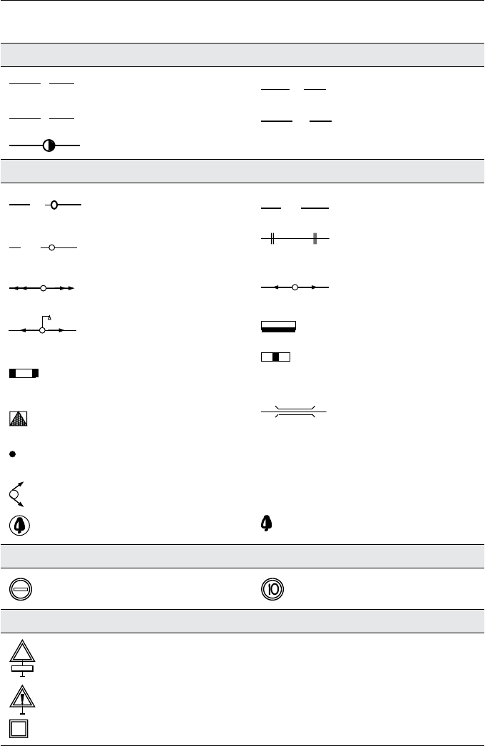
Appendix 175
WATER SUPPLY AND SEWERAGE
W
Existing water conduit
Temporary water
conduit
S
Existing sewerage
TS
Temporary sewerage
Fire hydrant well
ELECTRICITY SUPPLY
Temporary electric aerial
line on poles
Temporary
underground cable line
Temporary cable line on
poles
Cable line on trestles
Existing aerial line with a
voltage of ≥10 kV
Existing aerial line with
a voltage of ≤10 kV
Existing aerial line of
street lighting
Input-distribution
switchboard
Distribution switchboard for
switching power and lighting
equipment
Power supply of the crane
TT N°
Temporary transformer
substation
Cable in tube
Ν a/δ
Floodlight pole, where N – number on the layout, a – output,
δ – installing height
Floodlight or floodlight type lighting
⊗
General-purpose lighting
Existing trees for preserving
Existing trees for taking down
TRAFFIC SIGNS
No entrance
Maximum speed
RISK SIGNS
Warning sign with an explanatory text, eg ‘Crane in operation!’,
‘Falling objects!’, etc
Other risks!
Obliging signs. e.g. ‘Work with safety belt!’
TW
TC
TEP
TE

176 Appendix
SUPPLEMENTARY SYMBOLS
Up–coming building
E
Entrance
Temporary fence that
coincides with the planned
permanent fence
Board with construction
passport
G
Existing gas piping
Junction of temporary
utility network
Temporary light pole Permanent/planned light pole
Floodlight on pole
Floodlight on transportable
tripod

The Engineer’s Manual of Construction Site Planning, First Edition. Jüri Sutt, Irene Lill
and Olev Müürsepp.
© 2013 John Wiley & Sons, Ltd. Published 2013 by John Wiley & Sons, Ltd.
177
Bibliography
Bauer, H. (1994) Baubetrieb 2: Bauablauf, Kosten, Störungen. Aufl. Springer-Verlag,
Berlin.
Construction Site Workplace Safety Plan. Health and Safety Risk Management.
www.safety.com.au (accessed on 5 February 2013).
Ferguson, I. & Mitchell, E. (1986) Quality on site. B.T. Batsford Ltd., London.
Health and Site Executive. http://www.hse.gov.uk/construction/areyou/
cdmcoordinator.htm (accessed on 5 February 2013).
Hedfeld, K.-P. (1992) Wie organisiere ich meinen Baubetrieb Richtig? RKW RG-BAU,
Eschborn.
Illingworth, J.R. (1994) Construction Methods and Planning. E & PN Spon/Chapman&
Hall, London.
Mantscheff, J. (1991) Bauvertrags- und Verdingungwesen. VOB Teil A u.B. Werner-Verlag,
Düsseldorf.
Peurifoy, R.L., Schexsnayder C.J., Shapira A. & Schmitt R. Construction Planning,
Equipments and Methods. McGraw-Hill Education, New York.
Temporary Work Design. http://www.twd.nl/contact.html (accessed on 5 February
2013).
The Management of Temporary Works in the Construction Industry. http://www.hse.
gov.uk/contact/index.htm (accessed on 5 February 2013).
Dikman, L. Organizacija, planirovanije i upravlenije. Moscow: Vyshaja Shkola, 1982.

The Engineer’s Manual of Construction Site Planning, First Edition. Jüri Sutt, Irene Lill
and Olev Müürsepp.
© 2013 John Wiley & Sons, Ltd. Published 2013 by John Wiley & Sons, Ltd.
178
Index
allowable physical effort, 170
assembly work safety/assembly works,
68–76, 149
bidding stage, 15, 16, 20, 22, 23, 25, 26,
29, 46, 50
bill of activities, 5, 7, 8
bill of quantities, 2, 5, 7, 8, 17, 18, 35, 38, 46
calculation of duration, 8, 39, 41
construction site lightings, 24, 49, 126–7
construction market, description, xi
contractor, xiii–xv, 13, 17, 23, 41, 43, 47,
123, 138, 139, 141, 144, 146
responsibility, 138, 141, 146
technological possibilities, 17
cost estimation, xiii, 1, 15, 23, 25, 26, 29,
41, 46
crane danger and impact areas, 64, 65,
68, 69
crane track, 55, 59–62, 64, 65, 69,
72–4, 174
danger area (zone), 11, 19, 32, 33, 52, 53,
65, 66, 68–71, 89–96, 98, 142, 146–8,
153, 161, 163, 164, 166
demolition works / demolition work, 18,
21, 64, 137, 152, 153
design documents, 6–7, 12, 20
design phase, xiii, xv, 6
explosive materials, 140, 155, 162, 168
fencing, 11, 13, 20, 23, 24, 26, 32, 42, 45,
47, 64, 65, 100, 135, 136
first aid, 114, 143, 148, 171–2
flammable and explosive materials, 168
geometrical parameters on site plan, 34,
54, 59–63, 71
heating and power supply, 48, 116–25
impact area, 51, 64, 68, 69, 77, 87
impact of power line, 52, 91, 92, 94
initial data, xiii, 5, 28, 29, 46, 122, 124
labourer, 138–54, 156–62, 165–8,
170–172
labourer’s responsibility, 138, 144
lifting devices, (equipment), xiii, 10, 26,
31, 32, 47, 55, 64, 93, 157, 160

Index 179
lifting parameters of crane, 53, 55, 56, 72,
81, 84
lighting, xiii, 24, 26, 32, 33, 40, 45, 49, 100,
122, 124–7, 170, 175
load take up device, 47, 53, 55, 56, 75, 82,
100, 130, 131, 134, 135
methods of calculations, 124
mobile crane, 42, 47, 51, 77–9, 81,
83–91, 94
mobile equipment, 158–9
network chart, 29, 30, 36, 37, 39–41, 43
owner’s responsibility, 138, 139, 146
personal protective equipment, 143, 144,
147, 170–171
positioning of cranes, 51–5, 57, 60, 64, 74,
75, 85, 88, 94
power supply, 26, 33, 48, 100, 121, 162,
163, 175
productivity, 27, 38, 40, 43–5, 130
resource allocation, xiii, 3, 29, 33, 41
restrictions, 8–12, 38, 52, 53, 88, 96, 97,
105, 122, 141, 149
safety of underground works, 140,
147, 150, 171
safety requirements on site, 137
scaffolds, 155, 157, 165–7, 171
scale of layout, 20, 30
sequence of procedures, 32, 35
shift, 17, 23, 30, 33, 38, 40, 41, 47, 74,
130, 143
simultaneous operations, 51, 52, 71, 73–7
site inspection, 5, 8, 9, 14
site layout, 1, 13, 15, 16, 19–21, 25, 28–35,
41, 46, 53, 101, 107, 108, 111, 114–16,
122, 173, 174
site lighting, xiii, 24, 26, 32, 33, 40, 45, 49,
100, 122, 124–7, 170, 175
site storage, 19, 96, 99, 105, 108
specifications, 5, 7, 8, 161
technological model, 29, 36, 39, 41
temporary building, xiii, 1, 2, 10, 19, 21,
24, 26, 31, 33, 37, 42, 44, 48, 99, 106,
111, 113–15
temporary facilities, xiv, 19, 31
temporary heating, 99, 116–20
temporary power supply, 26, 48,
100, 121
temporary road, 2, 9, 11, 19, 23, 25, 26,
31, 47, 72, 99–104, 173
temporary water supply, 18, 23, 26, 48,
99, 115
temporary works, xiv, xv, 2, 15, 17, 23, 25,
27, 46, 50, 177
cost classification, 2, 17, 50
estimation, 23–7
tender, 6, 35
time schedule, xv, 1, 7, 13, 15–17, 21–4,
29, 33, 35, 41, 46, 122, 129, 142
tower cranes, 22, 31, 32, 42, 47, 51, 53–7,
59, 62, 63, 67–9, 71, 72, 74–7, 83, 85,
87–91, 96, 97, 105, 160, 174
transport on site, 100, 127–30
underground work, 140, 147,
150, 171
utility network, 2, 6, 11, 19, 23, 24, 30, 31,
42, 100, 101, 113, 114, 176
water supply, 18, 22, 23, 26, 33, 37, 44, 45,
48, 99, 115, 175
welfare facilities, 169, 171
work at height, 137, 140, 151, 155,
164, 165
work classification, 43, 44, 50
work equipment, 155–9, 162–5, 170
