
Computer Methods and Programs in Biomedicine 63 (2000) 47–54
Simulation of axonal excitability using a Spreadsheet
template created in Microsoft Excel
Angus M. Brown *
Department of Neurology, Uni6ersity of Washington School of Medicine, Box
356465
, Seattle, WA
98195
-
6465
, USA
Received 23 August 1999; received in revised form 23 January 2000; accepted 25 January 2000
Abstract
The objective of this present study was to implement an established simulation protocol (A.M. Brown, A
methodology for simulating biological systems using Microsoft Excel, Comp. Methods Prog. Biomed. 58 (1999)
181–90) to model axonal excitability. The simulation protocol involves the use of in-cell formulas directly typed into
a spreadsheet and does not require any programming skills or use of the macro language. Once the initial spreadsheet
template has been set up the simulations described in this paper can be executed with a few simple keystrokes. The
model axon contained voltage-gated ion channels that were modeled using Hodgkin Huxley style kinetics. The basic
properties of axonal excitability modeled were: (1) threshold of action potential firing, demonstrating that not only
are the stimulus amplitude and duration critical in the generation of an action potential, but also the resting
membrane potential; (2) refractoriness, the phenomenon of reduced excitability immediately following an action
potential. The difference between the absolute refractory period, when no amount of stimulus will elicit an action
potential, and relative refractory period, when an action potential may be generated by applying increased stimulus,
was demonstrated with regard to the underlying state of the Na
+
and K
+
channels; (3) temporal summation, a
process by which two sub-threshold stimuli can unite to elicit an action potential was shown to be due to conductance
changes outlasting the first stimulus and summing with the second stimulus-induced conductance changes to drive the
membrane potential past threshold; (4) anode break excitation, where membrane hyperpolarization was shown to
produce an action potential by removing Na
+
channel inactivation that is present at resting membrane potential. The
simulations described in this paper provide insights into mechanisms of axonal excitation that can be carried out by
following an easily understood protocol. © 2000 Elsevier Science Ireland Ltd. All rights reserved.
Keywords
:
Axon; Hodgkin Huxley; Ion channel; Microsoft Excel; Modeling; Simulation; Spreadsheet
www.elsevier.com/locate/cmpb
1. Introduction
This article is an extension of a previous study
that described in detail how to execute simula-
tions of biological systems using a spreadsheet
template created in Microsoft Excel [1]. The focus
* Tel.: +1-206-6168278; fax: + 1-206-6858100.
E-mail address
:
0169-2607/00/$ - see front matter © 2000 Elsevier Science Ireland Ltd. All rights reserved.
PII: S0169-2607(00)00076-6

A.M. Brown
/
Computer Methods and Programs in Biomedicine
63 (2000) 47 –54
48
of this present study was to implement that simu-
lation protocol to describe some fundamental
properties of axonal excitability based on the
squid giant axon containing a fast Na
+
current,
which results in the upstroke of the action poten-
tial, a delayed rectifier K
+
current, which results
in membrane repolarization, and an ohmic leak
current that determines resting membrane poten-
tial. The simulation uses the rate constants
derived by Hodgkin and Huxley [2] to describe
the voltage dependence of ion channel behavior,
although they have been updated to reflect mod-
ern conventions [1,3]. This simulation serves two
purposes. Firstly, it allows the user to conduct
simulations to investigate mechanisms of axonal
excitation in the squid giant axons. However,
other preparations can be modeled simply by
changing the appropriate rate constants and con-
ductances. Secondly, the user can study and
graphically display the underlying properties of
ion channels, such as activation, inactivation and
the resulting conductance changes, to see how
those properties determine axonal behavior.
Familiarity with the previous paper [1] is essen-
tial, as this present study uses it as a stepping
stone to demonstrate ‘real life’ scenarios. This
paper will be appreciated most by those who are
interested in carrying out interactive simulations
of ion channel behavior, but who do not wish to
expend the time and money necessary to learn
programming. The simulation involves using in-
cell formulas in which rows and columns of new
data are generated from key parameter values
typed into the spreadsheet, and solving a set of
equations based on those parameters. The fea-
tures of Excel that make it ideal for this purpose
are a user friendly interface, flexible data han-
dling, in-built mathematical functions and instan-
taneous charting of data. The objective of this
study was to use an established, easy to use
simulation protocol to demonstrate key features
of axonal excitability determined by ion channel
properties.
2. Computational method
Full details of the computational method illus-
trated in this present study have appeared previ-
ously [1]. The objective of the simulation was to
determine how the membrane potential of a
model squid giant axon containing I
Na
and I
K
,
responded to a variety of stimuli, i.e. it is a
current clamp simulation where changes in mem-
brane potential were modeled in response to con-
stant current injection. Each stimulus paradigm
was designed to illustrate an individual property
of axonal excitability. Briefly, the simulation is
carried out by (1) setting the initial membrane
potential, (2) setting the amplitude and duration
of current injection, (3) sequentially solving a
series of equations describing the rate constants,
(in)activation parameters, conductances, currents
and finally, change in membrane potential, respec-
tively, based on the initial values input by the user
in the first two steps. In current clamp simulations
the change in membrane potential (V) over time is
described by:
dV
dt
=
I
total
Cn
(1)
In the simulation described in this paper
I
total
=I
Na
+I
K
+I
leak
+I
inj
(2)
where
I
Na
=120m
3
h(− V+ 50) mAcm
−2
(3)
I
K
=36n
4
(− V− 77) mAcm
−2
(4)
I
leak
=0.3( −V −59.4) mAcm
−2
(5)
and I
inj
is the injected current input by the user.
The (in)activation parameters are described by
m(h, n)=
a
a+ b
(6)
rate constants for am, bm, an, bn, ah and bh can
be found elsewhere [1,3].
The spreadsheet template is illustrated in Fig. 1.
This template is identical to the one described
previously ([1], see Fig. 4 p. 186) and all the
expressions used in the calculations are the same
([1], see Table 2 p. 184). Each column contains the
solution of a separate voltage dependent parame-

A.M. Brown
/
Computer Methods and Programs in Biomedicine
63 (2000) 47 –54
49
ter (column B contains am, column C contains
bm, etc.). Column A contains the time parameter
where the time increment in 0.04 ms. The user
inputs the amplitude of injected current in cell B2.
Column P contains the data referring to injected
current. Thus, the duration of the current injec-
tion can be altered by increasing or decreasing the
number of rows in which it appears. In the first
row of calculations (row 4 on the spreadsheet) the
parameters are solved based on the initial value of
V input by the user in cell B1. In this instance it
is set to −70 mV. The calculations are carried
out sequentially from cell B4 to cell Q4. The I
total
(see Eq. (2)) is then used to calculate the new
membrane potential (V) in cell R4. The voltage
dependent parameters in the next row are solved
starting at cell B5 sequentially from B5 to Q5
using the new value of V in cell R4, and so on,
sequentially down the rows. In the following sim-
ulations only the value of current injection, initial
membrane potential or duration of current injec-
tion, were altered once the template has been set
up. These parameters can be altered as necessary
by changing values in cell B1, B2 or in column P,
respectively, to conduct the simulations described
below. The data of interest can be studied graphi-
cally, by plotting the time parameter (column A)
against the column containing the appropriate
data (e.g. for g
Na
, the data is in column K).
2
.
1
. Action potential threshold
The threshold, or critical depolarization, for
action potential firing is considered to be the
membrane potential above which regenerative de-
polarization occurs, resulting in the firing of an
action potential. Fig. 2A illustrates the calculated
time course of a uniformly propagated action
potential and the underlying Na
+
and K
+
con-
ductance changes. Note that the current injection
of 10 mA (C) causes an increase in g
Na
resulting in
depolarization of the membrane. This is followed
by a delayed increase in g
K
, which results in
repolarization of the membrane towards rest. The
increase in g
K
outlasts the duration of the stimu-
lus, a factor that is important in temporal summa-
Fig. 1. Spreadsheet template used to calculate V. The value for V in cell B2 is the initial membrane potential and is used in the
calculations in row 4. The value of V in cell R4 is then used as the voltage parameter in the calculations in row 5 to calculate the
new value of V. Calculations are carried out sequentially down the rows where the value for V calculated in column R of the
previous row is used in the calculations of the subsequent row to calculate the new value of V, and so on. Rows 14–503 have been
omitted to save space. At row 504 it can be seen that the value in column P has changed from 0 (no injected current) to 10 mA
reflecting the value of I
inj
in Cell B2.

A.M. Brown
/
Computer Methods and Programs in Biomedicine
63 (2000) 47 –54
50
Fig. 2. Stimulus evoked action potential. (A) The action
potential (bold) results from an increase in g
Na
, which depolar-
izes the membrane, followed by a delayed increase in g
K
,
which results in repolarization of the membrane. An after-hy-
perpolarization occurs due to g
K
outlasting g
Na
. (B) The total
conductance is plotted illustrating that when g
Na
is larger than
g
K
there is an increase in membrane conductance (arrow)
favoring a depolarization of the membrane. The faint line
illustrates sub-threshold stimulation for comparative purposes.
(C) The current injection of 10 mA of 5 ms duration used to
evoke the action potential.
ization increases. Finally the current injection is
sufficiently large (2.5 mA) to cause the all or
nothing action potential, due to the larger Na
+
conductance outbalancing the K
+
conductance.
Chronaxie is defined as the minimum duration of
twice the amplitude of rheobase needed to pro-
duce an action potential and is illustrated in Fig.
3B. This illustrates that both duration and ampli-
tude of current injection are important in deter-
mining if threshold is reached.
Threshold, however, is not a fixed value but
varies depending on axonal membrane potential
at the time of current injection (20 mA), a feature
illustrated in Fig. 4. It can be seen that for the
same amplitude of injected current, a larger g
Na
occurs at more hyperpolarized potentials ( −80
mV) than at depolarized membrane potentials
(− 60 mV; Fig. 4B). This is because hyperpolariz-
ing the axonal membrane removes Na
+
channel
inactivation, resulting in more available Na
+
channels. The current pulse recruits these addi-
Fig. 3. Rheobase and chronaxie. (A) The threshold current
required to elicit an action potential is 2.5 mA (the largest
illustrated current). Increasing sub-threshold pulses result in
increasing membrane potential changes. (B) Chronaxie is the
minimum stimulus duration required to elicit an action poten-
tial when applying a current of twice the rheobase (5 mA). In
this case the duration was 6.2 ms.
tion (see later). Fig. 2B illustrates the conductance
changes critical for action potential firing. In
terms of conductance, threshold is defined as the
potential at which inward Na
+
conductance is
greater than the outward K
+
conductance leading
to regenerative membrane depolarization. If the
K
+
current is larger than Na
+
current the mem-
brane potential will return to rest (faint trace),
however if the Na
+
current is marginally larger
that the K
+
current (arrow) membrane potential
will become unstable and produce an action po-
tential. This is explained in the Hodgkin cycle of
Na
+
excitability where depolarization of the
membrane leads to increased Na
+
permeability
resulting in net influx of Na
+
, which leads to
further membrane depolarization and so on [4].
Rheobase is defined as the minimum amount of
current required to produce an action potential [3]
and is illustrated in Fig. 3A. As the amplitude of
current injection increases so membrane depolar-

A.M. Brown
/
Computer Methods and Programs in Biomedicine
63 (2000) 47 –54
51
Fig. 4. The initial resting membrane potential determines the
profile of the action potential. (A) A hyperpolarized mem-
brane potential (−80 mV, bold trace) results in a larger action
potential than a more depolarized membrane potential (−60
mV, faint trace). (B) This is due to removal of Na
+
channel
inactivation resulting in larger g
Na
due to more available Na
+
channels, and decreased g
K
(not shown). (C) Current injection
of 20 mA for 5 ms.
Immediately after the first action potential h is
close to 0 indicating the majority of Na
+
channels
are inactivated, and n is close to 1, indicting that
the majority of K
+
are open, a fact reflected in
the hyperpolarized membrane potential immedi-
ately after the action potential. Thus there are two
factors which result in decreased excitability im-
mediately following an action potential; (1) the
majority of Na
+
channels are in the inactivated
state and unavailable for opening; and (2) the
Fig. 5. Refractory period. (A) The absolute refractory period is
the period immediately following an action potential when no
amount of current injection will elicit a second action poten-
tial. Top panel: the first action potential was elicited by a
current of 40 mA. Increasing this stimulus amplitude by an
order of magnitude failed to elicit a second action potential.
Middle panel: this is due to increased g
K
reflected in the value
of n near to 1, and the Na
+
channels still being in the
inactivated state, reflected by the value of h close to 0. Bottom
panel: the current injection profile. (B) The relative refractory
period occurs immediately after the absolute refractory period
when a second stimulus can elicit a second action potential but
the stimulus intensity must be increased. Top panel: a second
action potential can be elicited if an increased current is
injected (200 mA). The first action potential was elicited by 40
mA. The faint trace shows that a second current pulse of 40 mA
failed to elicit an action potential. Middle panel: The values of
n and h are returning towards rest when the second pulse is
injected. Bottom panel: the current injection profile.
tional Na
+
channels which are available at −80
mV but are inactivated at −60 mV, and hence
the increased g
Na
.
2
.
2
. Refractory period
Refractoriness is the period of decreased ex-
citability of an axon immediately after an action
potential. There are two types of refractoriness,
absolute and relative. The absolute refractory pe-
riod refers to the period immediately after an
action potential, when it is impossible to elicit a
further action potential no matter how much cur-
rent is injected. Fig. 5A illustrates this phe-
nomenon and its underlying mechanism. An
initial current injection of 40 mA for 1 ms elicits
an action potential. Repeating this stimulus 3 ms
later fails to elicit a second action potential, even
when current injection is increased by an order of
magnitude to 400 mA. The reason for this lack of
excitability is shown in the middle panel which
displays the K
+
channel activation parameter n,
and the Na
+
channel inactivation parameter h.
A.M. Brown
/
Computer Methods and Programs in Biomedicine
63 (2000) 47 –54
52
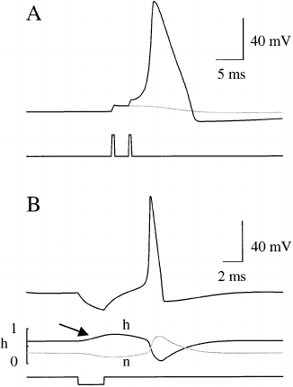
Fig. 6. Temporal summation and anode break excitation. (A)
The faint trace shows the effect of only one stimulus, which
fails to elicit an action potential. An action potential is elicited
when two sub-threshold stimuli are injected (bold trace). (B)
Injection of an anodal current pulse (bottom panel) results in
membrane hyperpolarization (top panel). ‘Breaking’ the an-
odal pulse results in membrane excitation culminating in an
action potential. Middle panel: This is due to removal of Na
+
channel inactivation (arrow indicates where h increases to-
wards 1 indicating reduction in Na
+
channel inactivation),
and decrease in g
K
reflected in a decrease in n towards 0.
2
.
3
. Temporal summation
This term usually refers to synaptic transmis-
sion where sub-threshold postsynaptic potentials
overlap and accumulate to drive the membrane
potential past threshold resulting in a postsynap-
tic action potential. Here the basic principal is the
same but the inputs are direct current injection
into the axon. This effect is demonstrated in Fig.
6A and shows how two sub-threshold stimuli of
40 mA amplitude and 200 ms duration delivered 1
ms apart can elicit an action potential (bold
trace), whereas a single stimulus of the same
dimensions fails to elicit an action potential (faint
trace). The stimulus-induced changes in mem-
brane conductance outlast the duration of the
stimulus, and it is possible for the conductance
changes brought about by the first stimulus to
sum with the conductance changes elicited by the
second stimulus if the interval between the two
stimuli is sufficiently small. The summed conduc-
tances can then drive the membrane potential past
threshold.
2
.
4
. Anode break excitation
This phrase refers back to the terminology used
in the 1940s where anodal current injection results
in a hyperpolarizing of the membrane potential.
The anode break refers to removal of a hyperpo-
larizing stimulus which gives rise to an action
potential. Thus, an action potential can fire even
after a current injection that results in membrane
hyperpolarization. The middle panel illustrates
the events underlying this phenomenon. As the
anodal current is injected, h, the Na
+
channel
inactivation parameter increases towards 1 signal-
ing that Na
+
channel inactivation is being re-
moved and more Na
+
channels are available for
opening. Conversely the activation parameter n,
for K
+
channels decreases towards 0 resulting in
decreased K
+
conductance. During the period of
anodal polarization there is a reduced outward
K
+
current and an increased Na
+
current. Thus
release of the polarization results in a membrane
depolarization that rapidly becomes regenerative
and results in threshold being reached and an
action potential firing.
majority of K
+
channels are open resulting in
hyperpolarization of the membrane.
The relative refractory period occurs after the
absolute refractory period and refers to the fact
that a second action potential can be elicited but
a larger current must be injected. This is illus-
trated in Fig. 5B. Delaying the interval between
the two stimuli to 8 ms permits current injection,
albeit of an increased amplitude (200 mA), to elicit
a second action potential (top trace). This is be-
cause the increased interval allows h to return
towards resting levels resulting in more Na
+
channels available for opening, and n decreases
(middle trace) resulting in less K
+
channels being
open resulting in a decreased level of membrane
hyperpolarization. A larger current pulse must be
injected to overcome the fact that neither n nor h
has returned to their resting levels.

A.M. Brown
/
Computer Methods and Programs in Biomedicine
63 (2000) 47 –54
53
2
.
5
. Repetiti6e firing
In 1928 Adrian outlined a theory of repetitive
firing [5], to describe how stimuli of increasing
strength resulted in increased frequency of action
potential firing. The objective of the Hodgkin
Huxley model was to describe membrane perme-
ability changes associated with a single action
potential, and predicts repetitive firing over a
limited range of frequencies in the squid giant
axon. Adding hypothetical K
+
conductances and
altering the voltage dependent properties of K
+
currents extends the range of firing frequencies to
more accurately describe the repetitive firing pat-
terns seen in squid giant axon [6,7]. However, for
demonstration purposes it is viable to use the
original Hodgkin and Huxley model to simulate
repetitive firing. Fig. 7 illustrates the property of
increased stimulus amplitude resulting in in-
creased action potential frequency. (A) Injecting a
current stimulus of 8 mA for 120 ms elicited a
pattern of seven evenly spaced action potentials
with inter-spike intervals of 17.8 ms. (B) Increas-
ing the stimulus amplitude to 20 mA decreased the
inter-spike interval to 11.8 ms, increasing the
number of action potentials to 11.
3. Discussion
In this paper current clamp simulations of ex-
citability of a model of the squid giant axon, a
classic electrophysiological preparation, are de-
scribed. The large diameter of the giant axon of
the squid Loligo allowed experimenters to insert
microelectrodes inside the axon to record ‘intra-
cellular’ responses of the axon and thus made it
an ideal preparation in which to study excitation
[8]. Subsequent investigation using the voltage
clamp technique allowed experimenters to control
the voltage of a piece of membrane and determine
ion movements at fixed voltages [9 –12]. These
data culminated in the classic description of Na
+
and K
+
permeability changes during excitation
and conduction in squid giant axon [2]. Hodgkin
and Huxley derived a series of equations that
accurately described the changes in permeability
in Na
+
and K
+
responsible for an action poten-
tial. Their model also predicted some basic prop-
erties of an excitable membrane, such as
refractoriness and anode break excitation de-
scribed in this paper. Why go to the trouble of
repeating the Hodgkin and Huxley model? The
model is still valid almost 50 years after its initial
description, and is widely used to describe behav-
ior of voltage-gated ion channels [13]. A great
advantage of the model is that it can be success-
fully applied to other preparations such as the
R15 neuron of Aplysia, which displays a more
complicated pattern of firing that the squid axon
[14]. The advantage of the protocol described in
this paper is that it does not require any program-
ming knowledge, which in today’s Windows based
environment, is costly and very time consuming.
It does not require the expense of purchasing
specialized software such as Neurosim [15], Neu-
ron [16] or Genesis [17]. It uses a spreadsheet on
a standard desktop PC which almost all biologists
know how to use, even if at an elementary level.
Such is the advance in technology that computa-
tion of an action potential which originally took 8
Fig. 7. Repetitive firing. (A) Injection of a 120 ms current
pulse of 8 mA (faint trace in C) produces repetitive firing in the
model axon. (B) Increasing the current amplitude to 20 mA
(bold trace in C) increases the number of action potentials
from 7 to 11. The scale bar represents 40 mV in A and B.
A.M. Brown
/
Computer Methods and Programs in Biomedicine
63 (2000) 47 –54
54
h on a hand held calculator can now be done in
under1sona400MHzPentium II computer with
64 MB RAM using the protocol described here.
References
[1] A.M. Brown, A methodology for simulating biological
systems using Microsoft Excel, Comp. Methods Prog.
Biomed. 58 (1999) 181–190.
[2] A.L. Hodgkin, A.F. Huxley, A quantitative description of
membrane current and its application to conduction and
excitation in nerve, J. Physiol. (Lond.) 117 (1952) 500–
544.
[3] B. Hille, Ionic basis of resting and action potentials, in: E.
Kandel (Ed.), Handbook of Physiology, American Physi-
ological Society, Bethesda, MD, 1977, pp. 99–136.
[4] A.L. Hodgkin, The ionic basis of electrical activity in
nerve and muscle, Biol. Rev. 26 (1951) 339–409.
[5] E.D. Adrian, The Basis of Sensation, Hafner, New York,
1928.
[6] F.A. Dodge, On the transduction of visual, mechanical,
and chemical stimuli, Int. J. Neurosci. 3 (1972) 5–14.
[7] B.I. Shapiro, F.K. Lenherr, Hodgkin –Huxley axon. In-
creased modulation and linearity of response to constant
current stimulus, Biophys. J. 12 (1972) 1145–1158.
[8] A.L. Hodgkin, B. Katz, The effect of sodium ions on the
electrical activity of the giant axon of the squid, J. Phys-
iol. (Lond.) 108 (1949) 37–77.
[9] A.L. Hodgkin, A.F. Huxley, B. Katz, Measurements of
current–voltage relations in the membrane of the giant
axon of Loligo, J. Physiol. 116 (1952) 424–448.
[10] A.L. Hodgkin, A.F. Huxley, Currents carried by sodium
and potassium ions through the membrane of the giant
axon of Loligo, J. Physiol. 116 (1952) 449–472.
[11] A.L. Hodgkin, A.F. Huxley, The components of mem-
brane conductance in the giant axon of Loligo, J. Physiol.
116 (1952) 473–496.
[12] A.L. Hodgkin, A.F. Huxley, The dual effects of mem-
brane potential on sodium conductance in the giant axon
of Loligo, J. Physiol. 116 (1952) 497–506.
[13] B. Hille, Ionic Channels of Excitable Membranes, Sinauer
Associates Inc., Sunderland, MA, 1992.
[14] C.C. Canavier, J.W. Clark, J.H. Byrne, Simulation of the
bursting activity of neuron R15 in Aplysia: role of ionic
currents, calcium balance, and modulatory transmitters,
J. Neurophysiol. 66 (1991) 2107–2124.
[15] P. Revest, Neurosim for Windows, Trends Neurosci. 18
(1995) 556.
[16] M.L. Hines, N.T. Carnevale, The NEURON simulation
environment, Neural Comput. 9 (1997) 1179–1209.
[17] J.M. Bower, D. Beeman, The Book of Genesis, Springer,
Berlin, 1995.
.
