
FINAL PROJECT REPORT
WECC WIND GENERATOR DEVELOPMENT
Prepared for CIEE By:
National Renewable Energy Laboratory
Project Manager: Eduard Muljadi
Authors: Edward Muljadi, Abraham Ellis
Date: March, 2010
A CIEE Report

i
Acknowledgments
The support of the U.S. Department of Energy (DOE), the Western Electric Coordinating
Council (WECC), and the California Energy Commissionʹs PIER Program are gratefully
acknowledged.
The author expresses his gratitude to the members WECC Wind Generator Modeling Group
(WGMG) and Model Validation Working Group (MVWG), General Electric, Siemens PTI who
have beeninstrumentalinprovidingtechnicalsupportandreviews,and, guidance during the
developmentofthisproject.
DISCLAIMER
This draft report was prepared as the result of work sponsored by the California Energy Commission. It does not necessarily represent the views
of the Energy Commission, its employees or the State of California. The Energy Commission, the State of California, its employees, contractors
and subcontractors make no warrant, express or implied, and assume no legal liability for the information in this report; nor does any party
represent that the uses of this information will not infringe upon privately owned rights. This report has not been approved or disapproved by the
California Energy Commission nor has the California Energy Commission passed upon the accuracy or adequacy of the information in this report.

ii
Preface ..
TheCaliforniaEnergyCommission’sPublicInterestEnergyResearch(PIER)Programsupports
public interest energy research and developme nt that will help improve the quality of life in
California by bringing environmentally safe, affordable, and reliable energy services and
productstothemarketplace.
ThePIERProgramconductspublicinterestresearch,development,anddemonstration
(RD&D)
projectstobenefitCalifornia.
The PIER Program strives to conduct the most promising public interest energy research by
partnering with RD&D entities, including individuals, businesses, utilities, and public or
privateresearchinstitutions.
PIERfundingeffortsarefocusedonthefollowingRD&Dprogram areas:
BuildingsEnd‐UseEnergy
Efficiency
EnergyInnovationsSmallGrants
Energy‐RelatedEnvironmentalResearch
EnergySystemsIntegration
EnvironmentallyPreferredAdvancedGeneration
Industrial/Agricultural/WaterEnd‐UseEnergyEfficiency
RenewableEnergyTechnologies
Transportation
ThedraftfinalreportfortheWesternElectricityCoordinatingCouncil(WECC)WindGenerator
Developmentproject (contractnumber500‐02
‐004,workauthorizationnumber MR‐065),is the
summaryofactivitiesreportedinseparate interimreports:
WINDPOWERPLANTEQUIVALENCING
WINDPOWERPLANTDATACOLLECTION
MODELVALIDATIONOFWINDTURBINEGENERATOR
This project is sponsored by the WECC‐WGMG, California Energy Commission (Energy
Commission),and the National Renewable Energy Laboratory
(NREL).Theinformation from
thisprojectcontributestoPIER’sEnergySystemsIntegrationProgram.
FormoreinformationaboutthePIERProgram,pleasevisittheEnergyCommission’swebsiteat
www.energy.ca.gov/research/
orcontacttheEnergyCommissionat916‐654‐4878.
iii
Table of Contents
Preface...............................................................................................................................................ii
AbstractandKeywords.....................................................................................................................vi
ExecutiveSummary...........................................................................................................................1
1.0 IntroductionandScope...........................................................................................................3
2.0 DescriptionofWindTurbineGeneratorTechnologies.......................................................5
Type1–Fixed‐speed,inductiongenerator...............................................................................5
Type2–Variableslip,inductiongeneratorwithvariablerotorresistance..........................6
Type3–Variablespeed,doubly‐fedasynchronousgeneratorswithrotor‐sideconverter6
Type4–Variablespeedgeneratorswithfullconverterinterface.........................................7
3.0 WindPowerPlantandPowerFlowEquivalencing............................................................8
4.0 WindPowerPlantData...........................................................................................................10
4.1Dataforsteady‐staterepresentation....................................................................................11
PowerFlowNetworkData................................................................................................11
4.2Datafordynamicanalysis.....................................................................................................12
TheprocessofcreatingadynamicfileforaWTG.........................................................12
4.3DataforWTGModelValidation..........................................................................................13
Infinitebusrepresentation.................................................................................................13
FieldMeasurementforDynamicDataforModelValidation......................................14
Theperphasevoltagewaveforms....................................................................................14
ProcessingDataforPSLFSimulation–ModelValidationExercise............................14
5.0 ModelValidationofWindTurbineGenerator....................................................................16
5.1Validationagainstthefieldmeasurements.........................................................................16
5.2Validationagainstthedetailed(manufacturerspecific)models.....................................17
6.0 SummaryandDissemination.................................................................................................19
7.0 FuturePlan................................................................................................................................20
References...........................................................................................................................................21
Glossary.............................................................................................................................................22
AppendixI‐ListofPublications.....................................................................................................I
AppendixII‐ListofShortCoursesandWorkshops....................................................................II
AppendixIII‐WindPowerPlantEquivalencing..........................................................................III
AppendixIV‐WindPowerPlantDataCollection.......................................................................IV
AppendixV‐ModelValidationofWindTurbineGenerator.....................................................V
iv
AppendixVI‐WECCWindPowerPlantPowerFlowModelingGuide..................................VI
AppendixVII‐WECCWindPowerPlantDynamicModelingGuide......................................VII
v
List of Figures
Figure1‐Fourdifferenttypesofwindturbinegenerator...................................................................5
Figure2‐PhysicaldiagramofatypicalWPP........................................................................................8
Figure3‐SingleturbinerepresentationforaWPP...............................................................................9
Figure4–Steadystateanddynamicdatagroupings.........................................................................11
Figure5‐Single‐machineequivalentimpedanceofNMEC‐WPP...................................................12
Figure6‐Dynamicmodelinputpreparation......................................................................................13
Figure7‐Theper‐phase‐voltagesvan,vbn,andvcnasrecorded........................................................14
Figure8‐Blockdiagramsindicatingtheflowprocesstoconvertthemonitoredvoltageintothe
inputdataforGENCLSmodule....................................................................................................15
Figure9‐InputdatatoGENCLStoperformthedynamicsimulation...........................................15
Figure 10‐Comparison between the generic model and the measured data for a Type 2 and
Type3WTG......................................................................................................................................16
Figure11‐ComparisonbetweenthegenericmodelandthedetailedmodelforaType1WTG.18
Figure12‐ComparisonbetweenthegenericmodelandthedetailedmodelforaType4WTG.18
vi
Abstract and Keywords
Windenergycontinuestobeoneofthefastest‐growingpowergenerationsectors.Thistrendis
expectedtocontinuegloballyasweattempttomeetagrowingelectricalenergydemandinan
environmentally responsiblemanner.Asthe number of wind powerplants (WPPs) continues
togrowandthelevelofpenetration
becomeshighinsomeareas,thereisanincreasedinterest
on the part of power system planners in methodologies and techniques that can be used to
adequatelyrepresent WPPs in interconnectedpower systemstudies.This project ispartof an
overall industry effort to develop, validate and implement generic positive‐
sequence stability
models forwind power plants (WPP).Although the modelsare designed specifically to meet
Western Electricity Coordinating Council (WECC) modeling requirements, the results also
benefittheindustryasawhole.Thesegoalsrepresentchallenges,someofwhich aredescribed
below:
There are currently four major different types of
wind generators, and all of them are
fundamentallydifferent fromconventionalgenerators.It isnecessary tohavedifferent
typesofwindturbinegenerator(WTG)dynamicmodelstocloselyrepresenteachofthe
fourtypes.
Wind turbine generators are a relatively new kind of technology where significant
technicalinnovationis
stilloccurring.Thus,planningmodelswerenotreadilyavailable
untilrecently.Fromanengineeringpointofview,representingWPPsasnegativeloads
or conventional generators is unacceptable.With the recent development and
implementation of WECC generic models of WTGs, wind power plants can now be
representedmoreproperly.
WPPsare
topologicallycomplex.Typicalplantshavehundredsofturbinesspreadover
averylargearea,interconnectedbymilesofradialfeedercir cuits,andfinallyconnected
to the utility grid at the point of interconnection (POI).In grid planning studies, it is
impracticaltorepresentthiscomplexsystemexplic itly.AlthougheachWPP
hasunique
characteristics(e.g.terminalvoltage,windcondition,lineimpedance,etc),itisnecessary
to find a reasonable equivalent representation that reproduces the important plant
behaviorasseenfromthePOI.
Validation of dynamic models is needed to verify that the models closely match the
dynamicbehaviorofactualequipment.
FieldmeasurementcanbeusedtovalidateWPP
models.Sincesuitablefielddataisdifficulttoobtain,modelverificationbycomparison
to manufacturer‐specific, higher‐order (more detailed), and validated dynamic models
canbeused.
Modelshavelimitedvalueunlesstheyarewelldocumentedandmadeavailabletogrid
plannersinthesimulationplatformsoftheirchoice.Forthisreason,thisprojectaimedat
implementing the models in simulation platforms that are typically used for grid
planning (GE PSLF and Siemens‐PTI PSSE).In addition, dissemination of the project

vii
results is accomplished via publications at the appropriate conferences, websites,
workshops,seminars,and,shortcourses.
In this report, we summarize the project which covers dynamic model development of four
typesofwindturbinegenerators,datacollectionneededformodelvalidation,powerflowwind
powerplantequivalencing,modelvalidation,andmodelingguidelines
developedforWECC.
Theinterimreportsareincludedasappendicesofthisfinalreport.Thegenericdynamicmodel
of four types of wind turbine generator has been implemented on two major power system
simulationplatforms:Siemens‐PTIPSSEandGeneralElectricPSLF.Theterm“generic”isused
toreferto
thedynamicmodelthatdoesnotcontainproprietaryinformationprotectedbywind
turbine manufacturers.These dynamic models of WTG are now part of the standard model
libraryinPSSEandPSLF.ThemodelingguidesarepubliclyavailableattheWECCwebsite
1
.
Keywords:Dynamicmodel,equivalencing,modelvalidation,windpowerplant,wind
turbine,windintegration,andsystemintegration.
1
http://www.wecc.biz/library/WECC%20Documents/Documents%20for%20Generators/Generato
r%20Testing%20Program/Wind%20Generator%20Power%20Flow%20Modeling%20Guide.pdf
- 1 -
Executive Summary
It is expected that large amounts of wind capacity will continue to be added to the power
system.The size of individual turbines has increased dramatically from a mere several
hundred kilowatts to multi megawatt turbines.The size of individual wind power plants
(WPPs)hasalsoincreased significantly.Inthepast,
atypicalWPPconsistedofseveralturbines.
Today, typical WPP nameplate capacity is 100MW to 200MW. Total capacity in a region or
clustercan reach 1 GW ormore.By some projections, asmuch as 20 GW ofadditional wind
generation capacity may be added in the Western Electricity Coordinating
Council (WECC)
footprintwithin thenext10–15years.Theincreaseinlevelofpenetration ofrenewableenergy
generation in the WECC region, and California in particular, poses significant challenges
concerningtheabilityofthepowersystemtomaintainreliableoperation.
For many years, lack of open access to adequate
models has resulted in much of the wind
capacity being modeled as conventional induction machines or negative loads in regional
planning studies.The increased use of this energy source necessitates a more accurate
representation of installed wind capacity.Misrepresentation of a WPP in a dynamic model
reducesconfidenceinthe
transmissionplanningprocessandcanleadtoerroneousconclusions.
Manufacturer‐specific, proprietary models are made available for interconnection studies;
however, their use is also challenging in practice.The overall goal of the generic modeling
effortistoaddressthesechallenges.
TheWindGeneratorModelingGroup(WGMG)hascompletedthefirstphase
developmentand
implementationof generic windturbine models.Fourgenericmodels produced bythis effort
represent the types of turbines that currently hold the largest market share in the North
American region. WECC is interested in ensuring that accurate and validated models of
standardwind turbines are readily available for
regionalstudies.This meansthat the models
should be suitable for inclusion in the WECC standard dynamic model database.The
availability of data sets for testing the models is critical to meet WECC’s model validation
requirements. WECC is also interested in guidelines discussing the methods of representinga
WPP in power
system studies. These goals are reflected in the functional guidelines of the
WECC WGMG.The WECC models will be generic in nature,that is,they donot require nor
revealproprietarydatafromtheturbinemanufacturers.
These improved, standard (i.e., generic, non‐proprietary) dynamic models would enable
planners, operators, and
engineers to plan and operate the system taking into account the
characteristics capabilities of modern wind turbines (e.g., dynamic, variable, reactive power
compensation, dynamic generation shedding capability, and soft‐synchronization with the
grid).Withtheappropriatedynamicmodelsavailableforwindturbines,plannerscouldmore
accuratelystudytransmissioncongestionorother
majorgridoperatingconstraints,eitherfrom
areal‐timegridoperationsortransmissionplanningperspective.Thesemodelscouldbeused
by transmission planners in expanding the capacity of existing transmission facilities to
accommodatewindenergydevelopmentinamannerthatbenefitselectricityconsumers.
- 2 -
This has become increasingly important as the penetration amounts of wind energy systems
have increased.The WECC‐WGMG efforts also provides opportunities for researchers at
universitiesandnationallaboratoriestomoreeasilyaccesstowindturbinemodelsandconduct
research.
This report is the final report for the WECC Wind Generator
Development Project, contract
number #500‐02‐004, work authorization number MR‐065, a project sponsored by the WECC‐
WGMG,CaliforniaEnergyCommission(EnergyCommission),andNationalRenewableEnergy
Laboratory(NREL).Thisreportsu mmarizestheactivitiesperformedinthisprojectasreported
intheinterimreports:
WindPowerPlantEquivalencing
WindPowerPlantDataCollection
ModelValidationofWindTurbineGenerator
TwoWECCguideswerepublishedbyWECC‐WGMG:
WECCWindPowerPlantPowerFlowModelingGuide
WECC Wind Power Plant Dynamic Modeling Guide (currently posted for comment
throughtheWECCModelingandValidationWorkGroup)
The
genericmodelsofwindturbinegenerators(Type1 –Type4)havebeendevelopedandare
now included in the standard model library of the PSSE and PSLF software platforms.The
generic models are also being implemented in two other software platforms: Operation
TechnologyETAP,andPowertechLabsDSATools.
Resultsfromthisprojecthavebeenwidely
disseminatedthroughpresentationsatworkshopsandshortcoursesconductedatmeetingsand
conferences sponsored by WECC, IEEE, Utility Wind Integration Group (UWIG), and
universities.Duringtheprogressofthisproject,technicalreports,andconferencepaperswere
alsopublishedatdifferentconferences.
‐3‐
1.0 Introduction and Scope
This report summarizes the results accomplished at the time of project conclusion.Before
WECC‐WGMG embarked on working on dynamic models of wind turbine generators,
availabilityofappropriatemodels forrepresentationofWPPswerelimited.Forthemostpart,
onlymanufacturer‐specificuser‐writtenmodelswereavailableonalimitedbasis
(throughnon‐
disclosureagreements)forthe purposesofconductinginterconnection studies.Thesetypesof
dynamic models are developed in full detail, including information deemed to be proprietary
by the turbine manufacturers.Manufacturer‐specific models sometimes are not fully
integrated into the standard model library of simulation software, which leads to
model
maintenance and compatibility issues.Also, difficulties sometimes occur when we want to
study an area with several WPPs from multiple manufacturers.Compatibility issues, limited
accessto modelsand longtechnical supportiterations often results inlong delaysto complete
the studies.After projects are completed, the proprietary nature of the
models prevents their
inclusion in the WECC standard dynamic database for the purposes of conducting regional
studies.
With funding from WECC, CEC and DOE, and support from several organizations including
DOE and Sandia, the WECC‐WGMG completed the first phase of the effort to develop and
implementwind turbine generator
(WTG)dyn amic models.The WECC dynamicmodels are
intended to be generic in nature and non‐proprietary, and thus are readily available for use.
Generic models allow for unique characteristics of WTGs from different manufacturers to be
represented by adjusting model parameters.These WECC dynamic models are currently
availableinthe
libraryofthePSLF(developedbyGE)andPSSSE(developedbySiemensPTI).
Default input data for each models is also provided.The generic models are also being
implemented in two other software platforms: Operation Technology ETAP, and Powertech
LabsDSATools.
Thisreportisorganizedasfollows:
Section1–IntroductionandProjectScope
Section2–Background
o Thissectionprovidesbackgroundofdifferenttasksconsideredinthisproject
Section3–DescriptionofFourdifferenttypesofWindTurbineGeneratorTechnologies
Section4–WindPowerPlantEquivalencing
o Thissectiondescribestheequivalencingmethodusedtorepresenthundredsof
turbinewithintheWPPasareducedmodelforbulksystemplanning.
Section5–WindPowerPlantData
o ThissectiondescribesthedataneededtosimulateandvalidateWPP.
Section6–ModelValidationofGenericModelsforWindTurbineGenerators
o ThissectiondescribesthemethodusedtovalidateWPP
Section7–SummaryandDissemination
‐4‐
o Thissectiondescribesthesummaryanddisseminationtothepublic
Section8–FuturePlans
o Thissectiondescribestheplantoexpandthemodelingeffort

‐5‐
2.0 Description of Wind Turbine Generator Technologies
Despitetheseeminglylargevarietyofutility‐sca leWTGsinthemarket,eachcanbeclassifiedin
one of four basic types, based on the generator topology and grid interface.The distinctive
topologicalcharacteristicsofeachtypeareshowninFigure1andarelistedbelow:
• Type1–Fixed
‐speed,inductiongenerator
• Type2–Variableslip,inductiongeneratorswithvariablerotorresistance
• Type3–Variablespeed,doubly‐fedasynchronousgeneratorswithrotor‐sideconverter
• Type4–Variablespeedgeneratorswithfullconverterinterface
Figure1‐Fourdifferenttypesofwindturbinegenerator
Type 1 – Fixed-speed, induction generator
The Type 1 WTG is an induction generator with minimal control.The torque speed
characteristic is very steep (about 1%slip at rated torque).There is no power semiconductor
switches used in this WTG in a normal running condition.The WTG absorbs reactive power
both in generating or motoring mode.The
reactive power required by the WTG is
compensated by mechanically switched capacitor bank (MSC).With a slow varying wind
‐6‐
speed,the MSC is able tofollow thereactive power variation andthe terminalvoltage is very
closelyregulated.Underfasttransients,theterminalvoltage maybela gginginresponseanda
wider voltage and output variation can be expected.Similarly, with sudden changes in
frequency, the output power may respond
instantaneously without any output current
restrictions,thus,afrequencyresponsesimilartoasynchronousgeneratorcanbeexpected.
Type 2 – Variable slip, induction generator with variable rotor
resistance
TheType2WTGisawoundrotorinductiongeneratorwiththecapabilitytoadjusttheeffective
externalrotorresistance.Theeffective valueoftheexternalrotorresistance isadjustablevia a
simplethree‐phasediode rectifier,DC chopper,anda parallelresistance.Thus effectively,the
WTGcanbecontrolledto
deliveraconstantratedpowerforwindspeedshigherthanratedby
adjustingthetotalrotorresistance.Belowratedwindspeeds(lowtomediumwindspeeds),the
operationof Type2 WTGsis verysimilar totheoperation ofType 1WTGs.In thehighwind
speed region, the WTG
generates constant output power, output currents, and output power
factor.Althoughtheexternalrotorresistanceiscapableof maintainingconstantoutputpowe r
at higher slips, the heat loss within the rotor resistance can be very high at higher slips.The
pitchcontrolleroftheWTGisusuallyadjustedtokeepthe
sliptobeascloseaspossibletothe
rated slip when the WTG operates in high wind speed.The WTG of this type tends to react
faster to sudden (transient) changes than WTG Type 1 because of its ability to maintain the
outputrealandreactive powerwiththe
adjustableexternalrotorresistanceandpitchcontroller.
Thus,asuddenwindgustdoesnotproducelargepowerandreactivepowersurges,norvoltage
dropslikewithType1WTGs.
Type 3 – Variable speed, doubly-fed asynchronous generators with
rotor-side converter
TheType3WTGisalsoknownasdoubly‐fedinductiongenerator(DFIG).Type3andType4
WTGs include a powerconverter to control the WTG.In a Type 3 WTG the rotor winding is
connected to the power converter and the stator winding is connected to the grid. Under
normal conditions or small transients, the power converter controls the output power of the
generator, reactive power or bus voltage.It can control the real and reactive power
independently and instantaneously.The power converter controls the stator output via
electromagnetic coupling between stat or and rotor separated by the air gap.
Under severe
disturbance (i.e., fault transients), the stator winding is exposed to abnormal and unbalanced
voltagedue tothefaultsthat occurin the transmissionlines.Asaresult,thepower converter
maylose its abilityto controlthe output of realand reactivepower,anditmay have toapply
thecrowbarmechanismtoprotecttheDCbusfromanovervoltagecondition.Thecrowbarin
effectisshortingtherotorwinding,thus,makingtherotorwindingappearlikeasquirrel‐cage
induction generator.The temporary imbalance between the aerodynamic power and the
electrical output power may accelerate the rotor
speed.To limit the rotor speed, the pitch
controlleradjuststhepitchangleofthebladestoavoidanoverspeedcondition.
‐7‐
Type 4 – Variable speed generators with full converter interface
For the Type 4 WTG, the power converter acts as a buffer between the grid and the electric
generator,thus,anytransientsoccurringinthegridarenottranslatedtotheelectricgenerator.
Undernormal or fault transients,the power convertercan be fullycontrolled.However, one
shouldrealizethat the
powerconverterhasa currentlimittoprotectth e outputcurrent ofthe
powersemiconductors(e.g.IGBTanddiodes),andwhenthegridvoltageislowduringafault
transient disturbance, the maximum output power that can be delivered to the grid is also
limited.Thus,thepitchcontrollerwill
limittherotorspeedfromover‐speedingavoidingarun‐
awaysituation.

‐8‐
3.0 Wind Power Plant and Power Flow Equivalencing
A typical modern WPP, as shown in Figure 2, consists of hundreds of turbines of the same
types.AWTGisusuall yratedatlowthreephasevoltageoutput(480–600V).Apadmounted
transformer at each turbine generator steps up the voltage to the medium voltage collector
system
(12 kV– 34.5kV).Several turbinesthat arephysically closetogetherare connectedto
laterallytoformagroup.Severalofthesegroupsareconnectedtoalargermainfeeder.Several
ofthese feeders areconnected tothesubstation wherethesubstation transformersteps up the
voltage to a
desired transmission level (e.g., 230 kV).A very large WPP can have several
substationtransformers.AnexampleofaWPPlayoutcanbeseeninFigure1.
POI or
connection
to the grid
Collector System
Station
Feeders and Laterals (overhead
and/or underground)
Individual WTGs
Interconnection
Transmission Line
Figure2‐PhysicaldiagramofatypicalWPP
Within a WPP, different turbines may operate under appreciably different conditions.Line
impedance connecting each wind turbine to the POI differs from each other.At a particular
instant in time, the wind speed experienced by one turbine can be significantly different from
anotherturbinelocatedatanotherpartoftheWPP.
ThediversityofaWPPisagoodattribute
inmanyways.Forexample,theoutputvariabilityoftheentireWPPisattenuatedwith respect
to the variability observed on a single wind turbine.The interaction between a WPP and the
grid is dete rmined by the collective behavior of the
WPP.In contrast, a conventional power
plantinteractswiththegridasasinglelargegenerator.

‐9‐
WPP equi valencing describes methods of equivalencing collector system in a large WPP.We
simplifieda WPP withmany windturbines intoasimplified turbine representation,asshown
inFigure3.
The full system representation (FSR) is a representation of WPP where every turbine is
represented along with the interconnecting collector system
connecting each turbine with
another,andconnectinggroupofturbinestothePOI.
Asingleturbinerepresentation(STR)isarepresentationofWPPwherea singleturbineisused
torepresent theentireWPP.Thisrepresentationismorepracticalforbulksystemsimulations.
Alatersectionofthereportwill
providetechnicaljustificationfortheuseoftheSTRinpower
flowanddynamicstabilitysimulations.Forvariousreasons,someWPPsmaycontaindifferent
types of wind turbines. Sometimes, a single WPP could have clusters that are very different
from the electrical connection point of view.For example, a portion of
the plant may be
connectedthroughalongoverheadfeeder,whileanotherportionoftheplantmaybeconnected
throughshortundergroundfeeders.ThisdiversityofWPPs,ifdeemedsignificant,canalsobe
represented with a model similar to the STR by defining distinct WTG groups, each of which
can
be modeled as an STR.Several methods of grouping considerations are also possible,
resulting in a multiple turbine re presentation (MTR) that can more accurately represent the
unique characteristics of a significantly diverse WPP.The interim report presented in
AppendixIIIdescribesmethodsusedtorepresentWPPsbyequivalenceinamore
lengthyand
detaileddescription.
W
Pad-mounted
Transformer
Equivalent
Wind Turbine
Generator
Equivalent
PF Correction
Shunt Capacitors
Collector
System
Equivalent
Interconnection
Transmission
Line
-
Plant-level
Reactive
Compensation
POI or Connection
to the Transmission
System
Station
Transformer(s)
1 2 3 4 5
Figure3‐SingleturbinerepresentationforaWPP
‐10‐
4.0 Wind Power Plant Data
The data required can be divided into two parts; the steady state data needed to solve the
powerflow portion ofdynamic simulation, andthe dynamic dataneeded tosolve the electro‐
mechanical interaction between the grid and the WTGs.A more detailed discussion about
windplantdatarequiredtosimulate
WPPandtovalidateaWTGdynamicmodelcanbefound
inAppendixIV.
The steady‐state data is mostly power system network data from the WPP and its reactive
power capability.This includes power factor correction capacitors at the WTG terminals or
reactivepowersupportequipment(e.g.,capacitors,STARCO M
orsimilar)locatedelsewherein
the WPP.Since a WPP consists of hundreds of turbines, the collector system is simplified by
equivalencingtheWPPintoasimplerepresentation(e.g.,singleturbinerepresentation).
The dynamic data consists of the generic model parameters for the specific WTG being
representedandplantlevelreactive
controls.
The wind turbine model requires the use of several modules corresponding to the
turbine type used in the simulation.Some of the model parameters may need to be
adjustedtomatchthecharacteristicsofeachturbinemanufacturer.
Specialflags andseveralparametervaluesoftheWTGmodulesneedtobesettoreflect
how the WTGs participate in the voltage/reactive power control strategy for the plant.
Some of the generic models require wind speed condition as an input to initialize the
pitchangle.
Other dynamic elements including reactive power support equipment are modeled
explicitly,usingconventionalmodels.
Thepowersystemnetworknormallyoperateswithinanarrow voltageandfrequencyenvelope.
Inanormalsituation,thevoltageandfrequencyatthebusesareatorveryclosetoratedvalues
(voltage= 1.0 per
unit,and frequency = 1.0 per unit).Equipment (i.e., loads)connected tothe
grid is designed to operate near rated frequency and voltage levels, with some tolerance to
allow for temporary excursions. The allowable voltage and frequency deviation is limited in
magnitude(range)andduration.Generallyandundernormalconditions,steady
‐statevoltage
is allowed to vary in a very limited range (max. 5% under normal conditions and 10% under
transientconditions).Steady‐statefrequencyvariationfollowsevenmorestrictlimits.During
transient events caused by faults or equipment switching, voltage and frequency can deviate
more significantly. The characteristics of the
system, including the network, generators and
load, determine whether the system is stable during steady‐state and transient conditions.
Steady‐stateanddynamicanalysisareperformedtomeasurethemarginofstabilityandpower
systemperformanceundertransientevents.
The WECC‐WGMG recommends the use of the single‐machine equivalent model
shown in
Figure 3 to represent WPPs in WECC base cases. This representation is recommended for

‐11‐
transient stability simulations and power flow studies.In Figure 4, the dashed line
circumscribes the power system elements that may requir e dynamic models.The solid line
circumscribesthepowersystemnetworkofaWPPrepresentation.
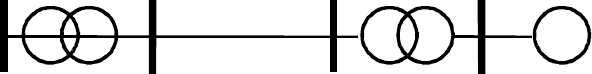
Figure4–Steadystateanddynamicdatagroupings.
4.1 Data for steady-state representation
The term steady state analysis in this section refers to the power flow or load flow analysis
commonlyperformedinpowersystemstudies.Thedatarepresentstheequivalentcircuitofthe
networktobeanalyzed,differenttypesofbusesi.e.,ageneratorbusorP‐Vbus,loadbusorP
‐Q
bus,andinfinitebusorswingbus.
Power Flow Network Data
Beforeproceedingwithmodelvalidation,itisnecessarytomodeltheWPPnetwork,andadjust
reactive power control strategy to reflect what is implemented in the field and match data
recordings. As an example, the WPP equivalent circuit for the New Mexico Energy Center
(NMEC) WPP is shown in Figure 5.
This equivalent is a single turbine representation.The
WPPconsistsof136turbineswithatotalcapacityof204MW.Eachwindturbineisratedat1.5
MW.Thewindturbineusedisavariable‐speedwindturbine(doubly‐fedinductiongenerator).
Mostof thecollecto r systems areunderground cables.
Themethod of equivalencing described
previously was used to find the equivalent impedances of the collector systems, the pad‐
mountedtransformer,andthestationtransformer.Thesystembaseusedis100MVA.
‐12‐
W
Pad-mounted
Transformer
Equivalent
Wind Turbine
Generator
Equivalent
Collector
System
Equivalent
Station
Transformer
B
WTG
Terminals
A
Transmission
Station
Req = 0.0135
Xes = j0.0497
Be
q
=
j
0.1004
C
R = 0.0027
X = j0.0245
R = 0.014
X = j0.0828
Figure5‐Single‐machineequivalentimpedanceofNMEC‐WPP
Since the WPP is controlled to keep the voltage at the POI and the voltage at the generator
terminal constant, the dynamic model was set to VARFLG = VLTFLG = 1.The regulated
voltage(busC)settingwasnotrecorded.WecanusethereactivepoweroutputatthePOIbus
A to determine the setting of the regulated bus voltage.After trial and error, we adjust the
regulatedvoltageatbusCsothattheoutputreactivepoweratbusAis23MVAR.
4.2 Data for dynamic analysis
Power system stability is defined as the ability of the system to reach equilibrium after a
disturbance with most system variables bounded so that practically the entire system remains
intact.Power system stability has been an area of interest since the initial development of
interconnectedpowersystems,particularlyfollowingtheadvent
oflong‐distancetransmission.
The importance of the subject cannot be overstated.Loss of stability can result in severe
economic,technical,andsocialupsets.
To study power systemstability, dynamic analysis is usually performed for the system under
investigation.In general, the dynamic data required is the input data for
the WTG.The
dynamicdataisusuallycontainedinaninputfilewithextension.dyd.Theinputfilewillhave
the description of the wind turbine dynamic modules with the appropriate input data for the
correspondingwindturbinetobesimulated.
The process of creating a dynamic file for a WTG
Theprocessofcreatingadynamicfile(.dydor.dyr)foraWPPisillustratedintheflowchart
showninFigure6.Itconsistsofseveralsteps:
1) Choosethe typeofwindturbinethatmatchestheplantwhosemodelisbeingvalidated
2) Select thecorrespondinggenericmodeland
inputparametersrelatedtotheturbines
chosen.
3) Select anappropriatemodelforplant‐levelcontrolreactivepowerequipmentinthe
plant.
4) Inmanycases,reactivepowercontrollabilityisprovidedbytheWTGsthroughaplant‐
levelcontroller(forWTGType3andType4).Thegenericmodelsfor
Type3andType

‐13‐
4WTGshaveemulatorsforplant‐levelcontrolsoptionsthatallowsforseveralcontrol
options.
a) Select voltagecontrolorpowerfactorcontrolorreactivepowercontrol,accordingto
whatisimplementedintheproject.
b) Ifthereisvoltagecontrolcapability(terminalvoltageandremotebus),specifythe
remotebus
thatiscontrolled.
4.3 Data for WTG Model Validation
Infinite bus representation
Forthepurposeofvalidation,thenetwork isrepresentedasanidealgeneratorconnectedtothe
POI through an equivalent impedance.We are using a facility in PSLF whereby a classic
generatormodel(GENCLSspecifically)canbeusedtoinjectameasuredvoltage andfrequency
tracesasawaytosimulate
atransienteventandcomparethemodelresponse(specifically,real
and reactive power) to field measurements.This technique has limitations, including
unbalancedsituations,lackofcompleteknowledgeofnetworkconditions,andthefactthatwe
are using a STR instead of MTR or FSR.Referring to Figure 6b, the ideal
generator is
represented by a generator classic GENCLS. This module allows the voltage and frequency
profilesto bespecified.Theinputdatatothismoduleisaninputfilecontainingthreecolumns.
Thefirstoneisthetimeindicator.Thesecondcolumnisthetimeseriesofvoltage,andthethird
columnisthetimeseriesofthefrequency.
Figure6‐Dynamicmodelinputpreparation
a) WTG
b) idealgenerator/infinitebus(faultsimulator)

‐14‐
Field Measurement for Dynamic Data for Model Validation
Field‐datameasurementcanbeusedtoverifyorvalidateadynamicmodel.Thefielddataisa
set of data measured at the POI.The data can be recorded at high sampling rates and the
recordingistriggeredbyatransienteventandusedtorecordtheeventfrompre
‐faulttopost‐
fault.Ideally, 10 to 20 seconds post‐disturbance data at sufficient resolution (20 samples per
secondorhigherifthe dataisRMS;7200 samplespersecondorhigherifthe dataispoint‐on‐
wave) is needed for model validation exercise.Typical fault recorders only capture
2 – 4
secondsofper‐phasevoltageandcurrentdata,whichismarginallyusefulformodelvalidation.
The model validation example below uses an actual 4‐seecond fault recording for the New
Mexico WPP described above.The location of data monitoring equipment is usually at the
substation POI.The data
measured is used to drive the simulation, and the response of the
windplantmodelsimulatediscomparedtotheactualmeasureddata.
The per phase voltage waveforms
It can be seen in Figure 7 that the three‐phase voltage currents van, vbn , and vcn recorded are
symmetricallybalancedvoltagesinthepre‐faultcondition.Thefaultoccursinthetransmission
lines in the vicinity of the WPP.It can be seen that the three‐phase voltage becomes an
unbalancedvoltage with phase B dropping significantly for a period offour cycles, before the
fault
iscleared.Thepost‐faultcondi t ion showsthatthethree‐phasevoltagesrecovertonormal
againandasmalloscillationisshownonthethree‐phasewaveforms.
0.9 0.92 0.94 0.96 0.98 1 1.02 1.04 1.06 1.08 1.1
-4
-3
-2
-1
0
1
2
3
4
x 10
5
Time (s)
Voltages (V) - Measured
Three Phase Voltages - 1
Figure7‐Theper‐phase‐voltagesvan,vbn,andvcnasrecorded
Processing Data for PSLF Simulation – Model Validation Exercise
ThegenericdynamicmodeltobevalidatedisavailableinPSSEandPSLFprograms. Touse
PSLFprogram,weneedtogettheinputdata todrivethesimulator.Theinputdatawillbethe
captured voltage waveform at the POI representing the fault and the outside power system
network.As
described earlier, the model validation strategy is to use the gencls PSLF model,
which can take positive‐sequence voltage magnitude and frequency as a function of time to
imposeasboundaryconditionsinthesimulation.Thus,conversionfromthesinusoidalvoltage
waveform into the positive‐sequence voltage magnitude and frequency
needs to take place.

‐15‐
The process of converting monitored voltage data into input data is ill ustrated in Figure 8.
MoredetailinformationcanbefoundinAppendixII.
Figure8‐Blockdiagramsindicatingtheflowprocesstoconvertthemonitoredvoltageintotheinput
dataforGENCLSmodule
Then the dq axis quantities in stationary reference frame are converted into a synchronous
referenceframe.Tousethedqvoltagefortheinputtotheprogram,weconvertthevoltagein
thesynchronousreference‐framephasorquantitiesusingthefollowingequation:
Sincethemodulesimulatingthevoltagesource
GENCLSusesthevoltagemagnitudeandits
frequency,weneedtoconvertthephaseangleinformationtothecorrespondingfrequency
changes.Thefrequencychangescanbecomputedfromthephaseanglechangesdividedbythe
timestep.
f(t)
qdet)
Positive‐sequencesimulationmodelsarenotdesignedtoaccuratelyrep roduceresponsetohigh
frequency components of the transient event (typical integration time step is approximately 4
milliseconds).For this reason, it is prudent to filter out these high‐frequency components in
voltage,frequencyandpowershouldbefilteredappropriately.
Finally,theinputdata(voltage
andfrequency)arereadytobeusedinmoduleGENCLSasshowninFigure9.Anexample of
aninputfilecontainingvoltageandfrequencyfortheGENCLSisgiveninAppendix2.
V and f
0.2
0.4
0.6
0.8
1
1.2
00.511.52
Time (s)
Voltage (p.u.)
0.95
0.99
1.03
1.07
1.11
1.15
Frequency (p.u.)
V
f
Figure9‐InputdatatoGENCLStoperformthedynamicsimulation
22
1
atan
qde qe de qde
de
qde
qe
VVV
V
V

‐16‐
5.0 Model Validation of Wind Turbine Generator
WTG needs to be validated to ensure that the behavior of the dynamic model reflects the
behavioroftheactualWTG.Thewindturbinemanufacturerusuallydevelopsadetailedmodel
of their turbine.This model contains detailed information considered proprietary by the
turbine manufacturer.The detailed model or manufacturer’s specific dynamic
model is not
releasedtothepublic,thus,theWECCgenericmodelsdevelopedinthisprojectaretheclosest
models to the detailed model without revealing the proprietary information embedded in the
detailed model.Thedetail model is usually validated rigorously by the turbine manufacturer
againstlaboratorymeasurementwithina
controlledenvironment,anditis consideredthebest
representation of the wind turbine.Ideally, the WECC generic dynamic models should be
validated by turbine manufacturers against field measurements.In addition, it is not always
easytogetfielddatameasurementfromtheWPPoperatororowner.Thus,asanalternativeto
using field measurement, you can compare the simulation of generic dynamic models to the
detailed models.A more detailed discussion on WTG Model Validation is presented in the
AppendixVofthisreport.
Figure10‐ComparisonbetweenthegenericmodelandthemeasureddataforaType2andType3
WTG.
5.1 Validation against the field measurements
The goal of this validation effort is to match the output of the dynamic model against actual
measurements captured at the transmission station, where disturbance recordings can be
‐17‐
obtainedrelativelyeasily.Thedisturbanceusedasanexampleinthisreportconsistsofaline‐
to‐groundfaultinthevicinityofthetransmissionstation,whichresultedinavoltagetransient
large enough to excite a significant dynamic response from the WPP, within the design
responsecapability of thegeneric
model (upto about 5Hz).Data before thefault occurred is
required to establish the pre‐disturbance power flow conditions that are used to initialize the
model.Thedisturbancerecordshouldextendseveralsecondsafterthecontingency,consistent
withthetimeframeofinterestofpositive‐sequencetransientstability
analysis.
An example of validation using measured data is presented in Figure 10.The validation
requires measured data to be preprocessed.The measured three phase voltage recorded at
highspeedispreprocessedtogetthevoltagemagnitudeandthefrequencyvariationduringthe
fault.The voltage and frequency waveform are used
to drive the simulation.The real and
reactive power outputs from the simulations are compared to the measured real and reactive
power.
5.2 Validation against the detailed (manufacturer specific) models
Inthissubsection,thevalidationofgenericdynamicmodelsagainstthedetailedmodelswillbe
presented.The generic dynamic models and the detailed models are simulated on the same
power system network, the same size of WPP, and using a prescribed fault event.The
simulation results from the two different dynamic
models are then compared, and the
difference is used to tune the parameters of the genericmodelsuntil the two dynamic models
generatesthesameoutputcharacteristics.
The dynamic models developed in this project are validated against the detailed dynamic
models by the model developers (Siemens Power Technologies International, and
General
Electric).The model developers have signed a non‐disclosure agreement with the turbine
manufacturerstodevelopthedetaileddynamicmodels.InFigure11,aType1WTG(induction
generator)fromaspecificturbinemanufacturerissimulated.Theoutputofthegenericmodel
iscomparedtotheoutputsimulationofthe
Type1WTGdetailedmodel.
Thedashedlineistheoutputsimulationofthedetailedmodel,andthesolidlineistheoutput
simulationofthegenericmodel.ItisshownthattheterminalvoltageVTERM,therealpower
output PELEC, the reactive power QELEC and the rotor speed SPEED
are all in agreement
betweenthegenericmodelandthedetailedmodel.
In Figure 12, the generic model of a Type 4 WTG is simulated and the simulation output is
compared against the detailed model of a Type 4 WTG when it is subjected to the same fault
eventusing the
samepower system network.The solidline representsthegenericmodeland
the dashed line represents the detailed model.The real power PELEC and reactive power
QELEC traces are shown and the signals are almost identical.Note, that the Type 4 WTG is
modeledbasedonfullpowerconversionthat
excludesthemodelingofthemechanicaldynamic
ofthewindturbine.

‐18‐
Figure11‐ComparisonbetweenthegenericmodelandthedetailedmodelforaType1WTG.
Figure12‐ComparisonbetweenthegenericmodelandthedetailedmodelforaType4WTG.
SPEED
QELEC
PELEC VTERM
PELEC QELEC
‐19‐
This project concluded with major accomplishments, including the completion of dynamic
modelsoffourtypesofwindturbinegeneratorsontwomajorpowersystemsoftwareplatforms
(PSLFandPSSE),modelvalidation ofthefourtypes ofWTGdynamicmodels, andtheWECC
modelingguides.
Theresultofthisprojectis
disseminatedinmanydifferentways.Currently,theGenericWTG
dynamicmodels(Type1–Type4)developedbySiemensPTIandGeneralElectricarepresently
includedinthesoftwarelibraryofthePSSEandPSLF.Inthepastmanypowersystemplanners
didnothaveanyoptiontomodelWPPother
thanrepresentingtheWPPasnegativeloadsora
simpleinductiongenerator.TheavailabilityofthedynamicmodelsoffourtypesofWTGgives
thepowersystemplannersbetteroptionstorepresenttheWPPcorrectly.
TheWECCPowerFlowGuide(2009)andWECCDynamicModelingGuide(tobecompletedin
2010) is accessible via the WECC website.This guide was developed by the Wind Generator
ModelingGroup(WGMG)oftheWECC.ThePowerFlowGuideiscurrentlyavailablefromthe
WECC website.The Dynamic Modeling Guide is currently being reviewed by the WGMG –
WECCanditwillbemadeavailable
fromtheWECCwebsite.
Workshops/short‐courses/seminars on WTG dynamic modeling were presented at various
eventssponsoredbytheIEEE,WECC,UWIG,IEC,andvariousuniversities.
Technicalpapersgiven attheIEEE,WindPower, andotherconferencesonrelatedtopics:WPP
equivalencing, fault analysis of a wind plant, WTG dynamic model
validation methodology,
powersystemstability,andshortcircuitbehaviorofWPP.
ThelistoftechnicalpapersandpublicationsrelatedtothisprojectislistedinAppendixI.The
listofworkshops,andshortcoursesisgiveninAppendixII.Aninterimreport describingthe
equivalencing is included in Appendix III, an
interim report describing the data collection is
givenin theAppendixIV,and theinterim reporton dynamicmodel validationis givenin the
AppendixV.CopiesofWECCguidesaregivenintheAppendicesVIandVII.
6.0 Summary and Dissemination
‐20‐
Thetopic of dynamicmodeling ofWPP needsto be expanded.Thiscontinuation is necessary
becauseofthewindtechnologyischangingrapidly−itrequirescontinuesmodeladaptationto
reflectthelatestturbine implementation.Parametersensitivities,identification,andtuning of
WTG dynamic models for differe nt manufacturers are needed to help
manufacturer derived
parametersforgenericdynamicmodelsrepresentingtheirturbines.
In the next phase, it is also necessary to revise/improve dynamic models to include droop,
ramp‐limit,reservemanagement,preprogrammedfrequency/inertialresponse,relayprotection.
Thesecapabilitieswillsoonbeimplementedbyturbinemanufacturersandtheexistingmodels
may have to be
upgraded to reflect new capabilities.Some of new turbine concepts may be
designedandinstalledinthenearfuture.Thenewturbineconceptshouldalsoberepresented
especiallyiftheirpresenceinthepowergridandthesizearesignificant.
In order to facilitate the adaptation of generic models by
other software vendors, we need to
support other software vendors (e.g., Powertech Lab, Inc., Operation Technology, Inc.) to
implementWTGdynamicmodelsontheirplatforms.
The availability and use of future PMU data collected by different agencies (WECC, BPA,
ERCOTetc) willbeaccessedtovalidatedynamicmodels,predictWPPstability,
designpossible
newWPPcontrolsandprotection.
Finally, we need to interact with the IEEE, the IEC, WECC, and UWIG for standard/guide
developmentandpublicdissemination.
7.0 Future Plan
‐21‐
References
[1] E.Muljadi,C.P.Butterfield,A.Ellis,J.Mechenbier,J.Hocheimer,R.Young,N.Miller,R.
Delmerico,R.Zavadil,J.C.Smith,”EquivalencingtheCollectorSystemofaLargeWind
PowerPlant”,presentedattheIEEEPowerEngineeringSociety,AnnualConference,
Montreal,Quebec,June12‐16,2006.
[2] E.Muljadi,B.Parsons,
ʺComparingSingleandMultipleTurbineRepresentationsina
WindFarmSimulation,ʺpresentedattheEuropeanWindEnergyConference(EWEC‐
2006),Athens,Greece,February27–March2,2006.
[3] N.W.Miller,J.J.Sanchez‐Gasca,W.W.Price,andR.W.Delmerico,“Dynamicmodeling
ofGE1.5and3.6
MWwindturbine‐generators forstabilitysimulations,”inProc.2003
IEEEPowerEngineeringSocietyGeneralMeeting,pp.1977–1983,June2003
[4] J.O.G.Tande,E.Muljadi,O.Carlson,J.Pierik,A.Estanqueiro,P.Sørensen,M.
O’Malley,A.Mullane,O.Anaya‐Lara,andB.Lemstrom.Dynamicmodelsofwindfarms
for
powersystemstudies–statusbyIEAWindR&DAnnex21,”EuropeanWindEnergy
Conference&Exhibition(EWEC),London,U.K.,Nov.22−25,2004.
[5] T.PetruandT.Thiringer,”Modelingofwindturbinesforpowersystemstudies,”IEEE
TransactionsonPowerSystems,Volume17,Issue4,Nov.2002,pp.1132–
1139.
[6] “GenericType‐3WindTurbine‐GeneratorModelforGridStudies”,Version1.1,
preparedbyWECCWindGeneratorModelingGroup,September14,2006
[7] “WECCWindPowerPlantPowerFlowModelingGuide”,preparedbyWECCWind
GeneratorModelingGroup,November2007
[8] P.C.Krause,AnalysisofElectricMachinery,McGrawHill
Co.NY,19862
‐ ‐
22
Glossary .
Thefollowingacronymsareusedinthisreport:
CEC CaliforniaEnergyCommission
CRPWM CurrentRegulatedPulseWidthModulation
DFAG DoublyFedAsynchronousGenerator
DFIG DoublyFedInductionGenerator
DOE DepartmentofEnergy
ERCOT ElectricReliabilityCouncilofTexas
FERC FederalElectricRegulatoryCommission
FOC FluxOrientedController
FPL FloridaPowerand
Light
FSR FullSystemRepresentation
IEC InternationalElectrotechnicalCommission
IEEE InstituteofElectricalandElectronicEngineers
LVRT LowVoltageRideThrough
NMEC NewMexicoEnergyCenter
NDA NonDisclosureAgreement
NEC NationalElectricalCode
NERC NorthAmericanElectricReliabilityCouncil
NREL NationalRenewableEnergyLaboratory
PFC PowerFactorCorrection
PIER
PublicInterestEnergyResearch
PNM PublicServiceofNewMexico
POI PointofInterconnection
PSLF PositiveSequenceLoadFlow
PSSE PowerSystemSimulatorforEngineers
RAS RemedialActionScheme
‐ ‐
23
SVC
Static VAr Compensator
TSR TipSpeedRadio
VAr Volt‐AmpereReactive
WECC WesternElectricityCoordinatingCouncil
WGMG WindGeneratorModelingGroup
WTG WindTurbineGenerator
WF WindFarm
WPP WindPowerPlant
‐ ‐
I
Appendix I - List of Publications
1. R. Piwko, E. Camm, A. Ellis, E. Muljadi, R. Zavadil, R. Walling, M. O’Malley, G. Irwin,
and, S. Saylors, “A Whirl of Activity”, the IEEE Power and Energy Magazine,
November/December 2009
2. D. Burnham, S. Santoso, E. Muljadi, “Variable Rotor Resistance Control of Wind
Turbine Generators,” presented at the IEEE Power Engineering Society, General
Meeting, Calgary, Alberta, Canada, July 26-30, 2009.
3. M. Singh, K. Faria, S. Santoso, E. Muljadi “Validation and Analysis of Wind Power
Plant Models using Short-Circuit Field Measurement Data,” presented at the IEEE Power
Engineering Society, General Meeting, Calgary, Alberta, Canada, July 26-30, 2009.
4. E. Muljadi, T. Nguyen, M.A. Pai, “Transient Stability of the Grid with a Wind Power
Plant,” to be presented at the IEEE Power System Conference and Exposition, Seattle,
WA, Mar. 15-18, 2009.
5. E. Muljadi, T. Nguyen, M.A. Pai, “Impact of Wind Power Plants on Voltage and
Transient Stability of Power Systems,” presented at the IEEE Energy2030 conference,
Atlanta, Georgia, Nov. 17-18, 2008.
6. A. Ellis, E. Muljadi, ”Wind Power Plant Representation in Large-Scale Power Flow
Simulations in WECC,” presented at the IEEE Power Engineering Society, General
Meeting, Pittsburgh, PA, July 20-24, 2008.
7. E. Muljadi, A. Ellis,” Validation of Wind Power Plant Dynamic Models”, invited panel
discussion presented at the IEEE Power Engineering Society, General Meeting,
Pittsburgh, PA, July 20-24, 2008.
8. E. Muljadi, Z. Mills, R. Foster, J. Conto, A. Ellis, ” Fault Analysis at a Wind Power Plant
for a One Year of Observation”, presented at the IEEE Power Engineering Society,
General Meeting, Pittsburgh, PA, July 20-24, 2008.
9. E. Muljadi, S. Pasupulati, A. Ellis, D. Kosterov,” Method of Equivalencing for a Large
Wind Power Plant with Multiple Turbine Representation”, presented at the IEEE Power
Engineering Society, General Meeting, Pittsburgh, PA, July 20-24, 2008.
10. R. Zavadil, N. Miller, A. Ellis, E. Muljadi, E. Camm, and B. Kirby, “Queuing Up”, the
IEEE Power and Energy Magazine, November/December 2007
11. E. Muljadi, C.P. Butterfield, B. Parsons, A. Ellis, ”Characteristics of Variable Speed
Wind Turbines Under Normal and Fault Conditions”, presented at the IEEE Power
Engineering Society, Annual Conference, Tampa, Florida, June 24-28, 2007.
12. M. Behnke, A. Ellis, Y. Kazachkov, T. McCoy, E. Muljadi, W. Price, J. Sanchez-Gasca
“Development and Validation of WECC Variable Speed Wind Turbine Dynamic Models
for Grid Integration Studies” presented at the Windpower 2007, WINDPOWER 2007
Conference & Exhibition, Los Angeles, CA, June 24-28, 2007.
13. E. Muljadi, C.P. Butterfield, B. Parsons, A. Ellis, “Effect of Variable Speed Wind
Turbine Generator on Stability of a Weak Grid”, published in the IEEE Transactions on
Energy Conversion, Vol. 22, No. 1, March 2007.
14. E. Muljadi, C.P. Butterfield, A. Ellis, J. Mechenbier, J. Hocheimer, R. Young, N. Miller,
R. Delmerico, R. Zavadil, J.C. Smith, ”Equivalencing the Collector System of a Large
Wind Power Plant”, presented at the IEEE Power Engineering Society, Annual
Conference, Montreal, Quebec, June 12-16, 2006.
‐ ‐
II
Appendix II - List of Short Courses and Workshops
1) WECC – 2009 Generator Model Validation Workshop, held at Tristate Generator and
Transmission Association, Westminster, CO May 18-19, 2009
2) WECC - 2009 Modeling Workshop for Planning Engineers, held at PG&E, San
Francisco, CA, April 16-17 2009
3) IEEE Dynamic Performance of Wind Power Generation Task Force (DPWPGTF)
“Tutorial on Wind Generation Modeling and Controls,” IEEE PSCE Conference, Seattle,
WA, USA – March 2009
4) Tutorial “Wind Energy Boot Camp” organized by New Mexico State University, PNM,
and NREL at Albuquerque, NM, Nov 12-14, 2008
5) IEEE Dynamic Performance of Wind Power Generation Task Force (DPWPGTF)
“Tutorial on Wind Generation Modeling and Controls,” IEEE PES General Meeting,
Pittsburgh, PA, USA – July, 2008
6) “WECC Wind Generator Modeling Project “, Policy Advisory Committee, California
Energy Commission (CEC), Irwindale, CA, 8/20/2007 and Kick off meeting for the, Los
Angeles, CA, 8/21/2007
7) “Wind Generator Modeling”, CEC-PIER-TRP Technical Advisory Committee Meeting,
Sacramento, CA, October 3, 2006
8) “Equivalencing Large Wind Power Plant”, WECC 2006 Modeling Workshop, Las Vegas,
NV, June 14-15, 2006
