
HELMET- 870257
Page 1 of 86
D3.1 High-Level Design Document
D3.1 High-Level Design Document
Due date of deliverable: 01/09/2020
Actual submission date: 01/09/2020
Leader/Responsible of this Deliverable: Omar Garcia Crespillo (DLR)
Reviewed (Y/N): Y
Document status
Revision
Date
Description
01
01/09/2020
1
st
Official Release
Dissemination Level
PU
Public
X
CO
Confidential, restricted under conditions set out in Model Grant Agreement
CI
Classified, information as referred to in Commission Decision 2001/844/EC
Start date of project: 02/01/2020
Duration: 24 months
This project has received funding from the European Union’s Horizon 2020 research and innovation programme under GA No 870257
Ref. Ares(2020)4537864 - 01/09/2020

HELMET- 870257
Page 2 of 86
D3.1 High-Level Design Document
CONTRIBUTING PARTNER
Name
Company
Roles/Title
Omar Garcia Crespillo
DLR
WP3 Leader & Contributor
Anja Grosch
DLR
Contributor
Matthias Fehr
DLR
Contributor
Chen Zhu
DLR
Contributor
Aleš Filip
UPA
Contributor
Filip Holík
UPA
Contributor
Alessandro Neri
RDL
Contributor
Maurizio Salvitti
RDL
Contributor
Cesare Dionisio
RDL
Contributor
Panagiotis Xefteris
RDL
Contributor
Pietro Salvatori
RDL
Contributor
Roberto Capua
SGI
Contributor
Luca Gattuso
SGI
Contributor
Manuele Innocenti
SGI
Contributor
Marco Giangolini
SGI
Contributor
Ondrej Kutik
RBA
Contributor
Miroslav Krajíček
RBA
Contributor
Michael Loupis
ITC
Contributor
John Spanoudakis
ITC
Contributor
DISTRIBUTION LIST
Name
Company
Roles/Title
Alessandro Neri
RDL
Project Coordinator
Daniel Lopour
GSA
GSA Programme Officer
Eutimio Tiliacos
GSA
Reviewer
Jose Eugenio Naranjo
GSA
Reviewer
Maurizio Salvitti
RDL
Project Manager
Aleš Filip
UPA
WP2 Leader
Omar Garcia Crespillo
DLR
WP3 Leader
Ondrej Kutik
RBA
WP4 Leader
Pietro Salvatori
RDL
WP5 Leader
Roberto Capua
SGI
WP6 Leader
APPROVAL STATUS
Document Code
Rev.
Role
Approved
Authorised
Date
HELMET_D3.1
01
WP3 Leader
O.Garcia Crespillo (DLR)
-
01/09/2020
Coordinator
A.Neri (RDL)
A.Neri (RDL)
01/09/2020

HELMET- 870257
Page 3 of 86
D3.1 High-Level Design Document
EXECUTIVE SUMMARY
This document is the deliverable D3.1 High-Level Design Document which describes the design
of the high-level HELMET architecture with focus on the main general architecture solutions for the
augmentation network subsystem as well as the general architecture solution for the onboard
subsystem for each transportation segments. This deliverable starts by reviewing the user and
system requirements as specified in deliverable D2.3. Then, it presents the HELMET high-level
architecture solutions for augmentation, rail, automotive and UAV at general subsystem level. The
general subsystem architecture is then used to convert the system and user requirements to the
subsystem level including the traceability matrix at subsystem level. This document then tackles the
identification of the technological gaps to satisfy such requirements. Finally, this document also
covers the high-level design of the record and playback unit that will be used during HELMET project.

HELMET- 870257
Page 4 of 86
D3.1 High-Level Design Document
TABLE OF CONTENTS
CONTRIBUTING PARTNER .................................................................................................................................. 2
DISTRIBUTION LIST ............................................................................................................................................ 2
APPROVAL STATUS ............................................................................................................................................ 2
EXECUTIVE SUMMARY ....................................................................................................................................... 3
TABLE OF CONTENTS ......................................................................................................................................... 4
LIST OF FIGURES ................................................................................................................................................ 6
LIST OF TABLES .................................................................................................................................................. 7
DEFINITION AND ABBREVIATIONS ..................................................................................................................... 8
1. INTRODUCTION ........................................................................................................................................... 12
2. REVIEW OF SYSTEM REQUIREMENTS .......................................................................................................... 13
2.1 Proposed System Requirements review and justifications ................................................................... 13
2.2 Summary of System Requirements ....................................................................................................... 15
3. HIGH-LEVEL MULTIMODAL SYSTEM DESIGN ............................................................................................... 17
4. MULTIMODAL AUGMENTATION INTEGRITY MONITORING HIGH LEVEL DESIGN ....................................... 18
5. HIGH LEVEL ARCHITECTURE FOR RAILWAY APPLICATION ........................................................................... 20
5.1 Railway principles used for safe architecture design ............................................................................ 21
5.2 Architecture_1: Reactive Fail-Safety for along track Train position determination ............................. 22
5.2.1 Markov model of reactive LDS ................................................................................................ 22
5.2.2 Derivation of Time to Fault Detection and Negation .............................................................. 24
5.2.3 Numerical verification of meaning of LDS state probabilities ................................................. 26
5.2.4 Interpretation of T
DN
as P
md
..................................................................................................... 27
5.2.5 Proposed Safety Monitor for run-time safety evaluation ....................................................... 28
5.2.6 Steps in Safety Monitor design ................................................................................................ 28
5.2.7 Example: Derivation of time to failure detection and negation (T
DN
) ..................................... 29
5.2.8 Example: Determination of P
md
for GNSS+AIMN-based ATP failure ....................................... 29
5.2.9 Example: MDE determination ................................................................................................. 30
5.3 Architecture_2: Composite Safety for Track Identification ................................................................... 31
5.3.1 Rules for realization of safety related functions with TFFR < 1e-9/ hour (EN 50129, IEC 61508)
33
5.3.2 AND-combination logic ............................................................................................................ 33
5.3.3 High-level composite LDS architecture for Track Identification based on track-side data ..... 34
5.3.4 Rail track-side infrastructure sensing ...................................................................................... 38
5.3.5 High-level composite LDS architecture for Track Identification in stand-still mode ............... 45
5.3.6 Cold Movement Detector in ERTMS baseline 3....................................................................... 47

HELMET- 870257
Page 5 of 86
D3.1 High-Level Design Document
5.3.7 Cold Movement Detector based on GNSS: proposed solution ............................................... 47
5.4 Overview of safety techniques Selection foR LDS ................................................................................. 48
6. HIGH LEVEL ARCHITECTURE FOR AUTOMATED VEHICLES APPLICATION .................................................... 49
6.1 General Approach and Considerations .................................................................................................. 49
6.1.1 High-level Architecture Design ................................................................................................ 50
6.2 High-level Localization Modes of Operation ......................................................................................... 51
6.3 Fault Tree Analysis for Automated Vehicles .......................................................................................... 52
7. HIGH LEVEL ARCHITECTURE FOR UAS APPLICATION ................................................................................... 56
8. CONVERSION OF SYSTEM REQUIREMENTS TO SUBSYSTEM LEVEL ............................................................. 62
8.1 AIMN Subsystem Requirements ............................................................................................................ 62
8.2 railway segment Subsystems Requirements ......................................................................................... 67
8.3 automotive segment Subsystems Requirements .................................................................................. 72
8.4 UAV segment Subsystems Requirements ............................................................................................. 74
9. TECHNOLOGY CAPABILITY GAPS.................................................................................................................. 77
10. RECORD AND PLAYBACK SYSTEM (RPS) ..................................................................................................... 79
10.1 System requirements decomposition ................................................................................................. 81
11. CONCLUSIONS ........................................................................................................................................... 84
12. REFERENCES ............................................................................................................................................... 85

HELMET- 870257
Page 6 of 86
D3.1 High-Level Design Document
LIST OF FIGURES
Figure 1: General design flow ....................................................................................................... 12
Figure 2: Overview of different design levels and their dependency .............................................. 13
Figure 3: In-lane vehicle localization/positioning ........................................................................... 14
Figure 4: Multi-modal positioning and localization system ............................................................. 17
Figure 5: Augmentation Network High Level Design ..................................................................... 18
Figure 6. Fail-safe techniques according to CENELEC: (a) composite fail-safety, and (b) reactive fail-
safety. ........................................................................................................................................... 21
Figure 7: Reactive LDS safety structure based on HELMET AIMN and independent diagnosis,
including Markov model ................................................................................................................ 23
Figure 8: Probability of failure as a function of HR
Non-Train(SIS)
and T
DN
............................................ 25
Figure 9: Safety monitor in FTA diagram. ...................................................................................... 27
Figure 10: Determination of Minimum Detectable Error (MDE) and maximal decision Threshold T
max
..................................................................................................................................................... 28
Figure 11: Determination of P
md
from duration of GNSS+AIMN-based ATP failure T
DN
................. 29
Figure 12: Markov model of two- channel LDS (2oo2) without failure detection ............................ 32
Figure 13: Principal composite safety LDS architecture intended for Track Identification function . 35
Figure 14: FTA of the LDS with composite safety: technical and operational safety measures have
been introduced to meet the required THR < 1e-9/ hr for main LDS hazard. ................................. 36
Figure 15: FTA of LDS with applied specific technical and operational safety measures. Examples
of minimum THR/TFFR requirements for individual functions in the composite solution are marked
in red) ........................................................................................................................................... 37
Figure 16: Train routing detection on switch by means of gyro-odometry: (a) based on double
heading differences (DHDs), and (b) complementary diagrams of heading differences for ride in
deflecting direction (above) and in straight direction . .................................................................... 39
Figure 17: Heading differences vs. travelled distance on the switch .............................................. 41
Figure 18: The posterior probability P(H
1
|A) of the routing detection vs. travelled distance on the
switch ............................................................................................................................................ 42
Figure 19. Fundamental elements of rail switch [12] ..................................................................... 42
Figure 20: Detection of guard rail to get information on train routing ............................................. 43
Figure 21: Switch with "self-guarding cast manganese" frog without guard rails [13] ..................... 43
Figure 22: Switch with movable frog without guard rails [14], [15] ................................................. 44
Figure 23: Principle of guard rail detection using laser sensor – works well in snow on track (tested
in operations) ................................................................................................................................ 44
Figure 24: Detection of guard rail using inductive proximity sensor ............................................... 45
Figure 25: FTA of composite safety LDS in case when train position is determined in stand-still .. 46
Figure 26: General Onboard unit Subsystem Architecture ............................................................ 50
Figure 27: General FTA Auto ........................................................................................................ 53
Figure 28: Auto Candidate solution 1 (FTA) .................................................................................. 54
Figure 29: FTA Analysis Positioning Auto (Candidate solution 2) .................................................. 55
Figure 30: UAV system architecture .............................................................................................. 56
Figure 31: Integrated functional architecture of UOBU for navigation ............................................ 59
Figure 32: UOBU conceptual design with two WFOW cameras .................................................... 60
Figure 33: UOBU conceptual simplified internal architecture ......................................................... 60
Figure 34: UOBU conceptual simplified internal architecture ......................................................... 61
Figure 35: Block diagram of ARCHITECTURE_1 with allocated subsystem requirements ............ 68

HELMET- 870257
Page 7 of 86
D3.1 High-Level Design Document
Figure 36: Block diagram of ARCHITECTURE_2 with allocated subsystem requirements ............ 70
Figure 37: Sensor and Recording unit architecture ....................................................................... 80
LIST OF TABLES
Table 1: Summary of Localization system requirements ............................................................... 16
Table 2: Localization Modes of Operation ..................................................................................... 52
Table 3: Preliminary operation modes supporting application scenarios ....................................... 52
Table 4: Augmentation System Service Level Definition ............................................................... 63
Table 5: Level to Augmentation Systems allocation ...................................................................... 64
Table 6: Augmentation Subsystem Requirements Review ............................................................ 64
Table 7: System Requirements for Localization System Rail – ARCHITECTURE_1 ..................... 68
Table 8: System Requirements for Localization System Rail – ARCHITECTURE_2 ..................... 71
Table 9: Subsystem requirements for Localization System Automotive ......................................... 72
Table 10: Subsystem requirements for Localization System UAS ................................................. 74

HELMET- 870257
Page 8 of 86
D3.1 High-Level Design Document
DEFINITION AND ABBREVIATIONS
Acronym
Description
A
Availability
ABIA
Avionics Based Integrity Augmentation
ADS-B
Automatic Dependent Surveillance - Broadcast
AIMN
Augmentation and Integrity Monitoring Network
AL
Alert Limit (defined by user)
ARAIM
Advanced Receiver Autonomous Integrity Monitor
ASIL
Automotive Safety Integrity Level
ATP
Along Track Position / Positioning
ATPL
Along Track Protection Level
BTM
Balise Transmission Module
CAN
Controller Area Network
CC
Control Center
CCF
Common Cause Failure
CCS
Control Command and Signalling
CCS TSI
Control Command and Signalling Technical Specifications for
Interoperability
CENELEC
Comité Européen de Normalisation Électrotechnique
CGS
Control Ground Station
CHK
Check
CMD
Cold Movement Detector / Detection
CNPC
Control and Non-Payload Communications
CONOPS
Concept of Operations
DaA
Detection and Avoidance
DB
Track Database
DCB
Differential Code Bias
DHD
Double Heading Differences
DTE
Driving Technical and control Error
E/E/PE
Electrical/Electronic/Programmable Electronic
EDAS
EGNOS Data Access Service
EGNOS
European Geostationary Navigation Overlay Service, i.e. European
SBAS
EM
electro magnetic
ERSAT GGC
ERTMS on SATellite – Galileo Game Changer
ERSAT-EAV
ERTMS on SATellite – Enabling Application & Validation
ERTMS
European Rail Traffic Management System
ETCS
European Train Control System
EU
European Union
EUREF
IAG Reference Frame Sub-Commission for Europe
EVC
European Vital Computer
FDE
Fault Detection and Exclusion
FDIR
Fault Detection, Isolation and Recovery
FEE
Front End Electronics
FOG
Fibre Optic Gyroscope

HELMET- 870257
Page 9 of 86
D3.1 High-Level Design Document
FR
Failure Rate
FTA
Fault tree Analysis
Galileo
European GNSS
GBAS
Ground Based Augmentation System
GCS
Ground Control Station
GEO
Geostationary Earth Orbit satellite
GNSS
Global Navigation Satellite System
GNSS Rx(rx)
GNSS Receiver
GPS
Global Positioning System
GRSP
Galileo Reference Service Provider
GSA
European Global Navigation Satellite Systems Agency
HAS
High Accuracy Service
HELMET
High integrity EGNSS Layer for Multimodal Eco-friendly
Transportation
HR
Hazard Rate
HPL/VPL
Horizontal/Vertical Protection Level
IMTM
Inspection, Monitoring and Traffic Management
IMTM UAS/RPAS-PI
Inspection, Monitoring and Traffic Management + Unmanned Aircraft
System / Remotely Piloted Aircraft Systems. In this PIT station the
UA/RPA can land and refuel batteries based for instance on a non
contact equipment.
IMU
Inertial Measurement Unit
INDEP-CHK
Independent Check
INS
Inertial Navigation System
K
fa
Coefficient of False Alert
K
md
Coefficient of Missed Detection
KVH FOG
KVH (i.e. name of company) Fibre Optic Gyroscope
LDS
Location Determination System
LiDAR
Light Detection and Ranging
LNA
Low-Noise Amplifier
MA
Movement Authority
MDE
Minimum Detectable Error
MEMS
Micro Electro Mechanical Systems
METEO
Meteorological Conditions
MFMC
Multi frequency Multi-constellation
MI
Misleading Information
MOBU
Multi-sensor On-Board Unit platform
MTBF
Mean Time Between Failure
MTTF
Mean Time to Failure
MTTR
Mean Time to Repair
NAV
Navigation
NAVAIDS
Navigational Aids
NLOS
Non-line-of-sight reception
NMEA
National Marine Electronics Association
NP
No Power
NRTK
Network RTK
NTRIP
Networked Transport of RTCM via Internet Protocol

HELMET- 870257
Page 10 of 86
D3.1 High-Level Design Document
OBU
On-Board Unit
PF
Probability of Failure (average) per 1 hour
PHMI
Probability of Hazardously Misleading Information
PIT-Station
On ground Service Station
PL
Protection Level
Pmd
Probability of Missed Detection
PPK
Post-Processing Kinematics
PPP
Precise Point Positioning
PPP-AR
PPP Ambiguity Resolution
PPS
Pulse Per Second
PTP
Precision Time Protocol
PVT
Position, Velocity, Time
QoS
Quality of Service
RAIM
Receiver Autonomous Integrity Monitor
RBC
Radio Block Centre
RF
Radio Frequency
RHINOS
Railway High Integrity Navigation Overlay System – H2020 project
RIMS
Ranging Integrity Monitoring Stations
RIU
Receiver Interpolation Uncertainty
RNP
Required Navigation Performance
RPS
Remote Pilot Stations
RS
Reference Station network
RTCM
Radio Technical Commission for Maritime Services
RTK
Real Time Kinematics
RTM
Requirements Traceability Matrix
RXFE
Receive Front End
SBAS
Satellite Based Augmentation System: e.g.: EGNOS, WAAS, MSAT,
SDCM, GAGAN
SDC
Self-Driving Car
SDR
Software-Defined Radio
SDT
Safe Down Time
SIL
Safety Integrity Level
SIS
Signal-In-Space
SNR
Signal to Noise Ratio
SoL
Safety of Life
SOM
Start of Mission
SR
Staff Responsible
SSR
State Space Representation
SW
Software
TDN
Time to failure Detection and Negation
TFFR
Tolerable Functional Failure Rate
THR
Tolerable Hazard Rate
TPL
Train Position Locator
TT&C
Telemetry, Tracking & Command
TTA
Time-To-Alert
U
Unavailability

HELMET- 870257
Page 11 of 86
D3.1 High-Level Design Document
UA/RPA
Unmanned Aircraft/ Remotely Piloted Aircraft
UART
Universal Asynchronous Receiver/Transmitter
UAS
Unmanned Aircraft System
UAS/RPAS
Unmanned Aircraft System / Remotely Piloted Aircraft Systems
UAV
Unmanned Aerial Vehicle
UNISIG
Union Industry of Signalling
UOBU
UAS On Board Unit
UTM
Unmanned Aircraft System Traffic Management; UAV Traffic
Management
VB
Virtual Balise
VBN
Visual Based Navigation
VBR
Virtual Balise Reader
VTOL
Vertical Take-Off and Landing
WFOV
Wide Field of View
ZTD
Zenith Tropospheric Delay

HELMET- 870257
Page 12 of 86
D3.1 High-Level Design Document
1. INTRODUCTION
In deliverable D2.3 the user and system requirements are defined and specified. The architecture of
the system from multiple levels is designed progressively based on the requirements, as shown by
the dependency diagram in Figure 1.
User Requirements
User Functional
Requirements
System Requirements
High Level System
Design (D3.1)
Functional Architecture
Design (D3.2)
Detailed Design (D3.3)
Figure 1: General design flow
Based on the user and system requirements, the multimodal positioning and localization system
architecture is proposed so that the requirements can be fulfilled. Figure 2 clarifies the division of
different hierarchies used for the system design. The high level design implies the architecture on
the system and subsystem level in the context.

HELMET- 870257
Page 13 of 86
D3.1 High-Level Design Document
Figure 2: Overview of different design levels and their dependency
2. REVIEW OF SYSTEM
REQUIREMENTS
This section reviews and summarizes the system level requirements from D2.3 [2] related to the
vehicle localization system.
2.1 PROPOSED SYSTEM REQUIREMENTS
REVIEW AND JUSTIFICATIONS
The System Requirements for the multi-modal HELMET solution have been derived from the
HELMET high-level User Requirements, with the identification of constraints and limitations,
specifying models and architectures of RAIL, AUTO and UAVs in order to perform an accurate safety
analysis.
The requirements of railway applications are specified in section 5.1 of D2.3 [2]. Compared with the
railway application, the road traffic has more diversity in the vehicles and environments, which also
results in diverse requirements. The system requirements as functions of vehicle dimensions as well
as the road and lane width are analysed in section 5.2 of D2.3 [2]. In this section, we calculate
specific quantitative requirements for automotive with some typical values in order to better guild the
following system design and development.
The most demanding requirement comes from the lateral dimension of the in-lane vehicle
localization, which is defined by the following equation in D2.3 (and illustrated by Fig. 2) [2]:
where
and
are the width of the lane and the vehicle respectively, and
is the
maximum driving technical and control error.

HELMET- 870257
Page 14 of 86
D3.1 High-Level Design Document
Figure 3: In-lane vehicle localization/positioning
In order to align the common requirements on the localization system in different traffic models, we
investigate the specified requirements according to typical values of the parameters in Europe.
Concerning the EU road definition, application, velocity, dimensions, presence of traffic lights / tolling
stations have to be taken into account.
Although different road design principles are adopted in single countries, a typical width of 3,50 m to
3,75 m (https://ec.europa.eu/transport/road_safety/sites/roadsafety/files/pdf/ersosynthesis2018-
motorways.pdf) is considered in Europe. According to the following link about European lane widths
(https://en.wikipedia.org/wiki/Lane), it could be assumed:
▪ V (highway/local/narrow) = 80-130 / 60-90 / 20-60 [km/h]
▪ Width lane (highway/local/narrow) = 3.75 / 3.25 / 2.75 [m]
The lane width is of particular interest mainly in the derivation of the lateral AL and correspondent
accuracy.
About the car sizes, we have to try to adapt the needs to the European car market: from the following
link (https://www.automobiledimension.com/car-search-engine.php), searching for cars with
maximum width W, length L and height H, the maximum values obtained are (usually related to a
VAN vehicle):
W / L / H = 1.986 / 5.4 / 1.977 [m] ≤ 2 / 5.4 / 2 [m]
For longitudinal dimension, the main constraint on longitudinal AL comes from the curves, where the
vehicle must ensure to keep itself in the lane when passing these parts of the highway. More detailed
analysis can be found in D2.3 [0], which results in the following equation and table:
The curve radius of the road depends on the road type and might differ from country to country.
The minimum allowed radii are in relation to the designed speed requirement of the road has already
been provided in Table 13 from D2.3 [2]. In addition, on local and narrow road, there is an additional
Car width
Lane width

HELMET- 870257
Page 15 of 86
D3.1 High-Level Design Document
requirement that the vehicle must stop at least one meter before any crossing or traffic light. Hence,
the AL for longitudinal AL is set no smaller than one meter. For highways, there is no such constraint.
Exploiting the following typical values from our analysis and references as input data for the above
reviewed equations from D2.3 [2]:
▪ W
veh
/ L
veh
= 2 / 5.4 [m] (on the basis of the maximum dimensions currently available derived
by the above link)
▪ Wlane (highway/local/narrow) = 3.75 / 3.25 / 2.75 [m]
▪ Minimum road radius (highway/local/narrow) = 240 / 120 / 10 [m]
▪ DTE
max
= 0.2 [m]
we obtain the values listed in the Table 1 “Summary of Localization System Requirements”.
It can be seen that with a narrow road width less than 3 m, the AL and positioning accuracy
requirements might be challenging to achieve with high availability by considering the currently
available technologies. We will further mention this point in the technology capability gap section
(section 9).
The integrity risk for automated driving should not exceed 1e-6, according to the report from GSA
[16]. From the integrity risk and the alert limit we can derive the corresponding 95% accuracy
requirement. In HELMET we will investigate if it is possible to achieve even higher integrity to further
ensure safety.
2.2 SUMMARY OF SYSTEM REQUIREMENTS
According to the review and justification in the last section, the system requirements for different
models are summarized in Table 1.

HELMET- 870257
Page 16 of 86
D3.1 High-Level Design Document
Table 1: Summary of Localization system requirements
Application
Scenario
User requirement / Use case
Integrity
Accuracy 95%
Alert Limit
Time-to-Alert
Availability
Continuity
Security
RAIL
Localization
system
Track Identification
<1e-9/h
0.7 m
(SR-OBU-PER-006.a)
1.785 m
(SR-OBU-SAF-
005.a)
10s - 30 s
(SR-OBU-FUN-007.a)
High
NA
Very high
Odometry Calibration
<1e-9/h
0.7 m
(SR-OBU-FUN-010.a)
1.7 m
(SR-OBU-SAF-
011.a)
< 1 s
(SR-OBU-SAF-012.a)
High
NA
Very high
Cold Movement Detection
<1e-9/h
2 m
(SR-OBU-FUN-014.a)
5 m
(SR-OBU-SAF-
013.a)
< 10 s
(SR-OBU-SAF-015.a)
High
NA
Very high
AUTO
Localization
system
Automated Driving on
Highway
1e-6/h
27.6 cm lat
(SR-OBU-PER-103.a)
4.58 m long
(SR-OBU-PER-108.a)
67.5 cm lat
(SR-OBU-SAF-
102.a)
11.2 m long (SR-
OBU-SAF-117.a)
1 s
(SR-OBU-SAF-108.a)
> 99.5%
(SR-OBU-SAF-
110.a)
High
(SR-COM-SAF-
120.a)
Very high
(SR-OBU-
SEC-111.a)
Automated Driving on Local
Roads
1e-6/h
17.38 cm lat
(SR-OBU-PER-105.a)
40.9 cm long
(SR-OBU-SAF-118.a)
42.5 cm lat
(SR-OBU-SAF-
104.a)
1 m long
1 s
> 99.5%
High
Very high
Automated Driving on Narrow
and Curved Roads
1e-6h
7.16 cm lat
(SR-OBU-PER-107.a)
11.86 cm long
(SR-OBU-PER-112.a)
17.5 cm lat
(SR-OBU-SAF-
106.a)
29 cm long
(SR-OBU-SAF-
119.a)
1 s
> 99.5%
High
Very high
UAV*
Localization
System
Monitoring Mission
1x10⁻⁷/h to
2x10⁻⁷/h
1 m /10m hor & vert
~m
1 s
95%-99%
1x10⁻⁴/h to 1x10-
8/h
Very high
Inspection Mission
1x10⁻⁷/h to
2x10⁻⁷/h
1 m /10m hor & vert
~m
1 s
95%-99%
1x10⁻⁴/h to 1x10-
8/h
Very high
Traffic Management Mission
1x10⁻⁷/h to
2x10⁻⁷/h
10m / 30m hor & vert
~m
1 s
95%-99%
1x10⁻⁴/h to 1x10-
8/h
Very high
*: Respective system requirement in section 5 of deliverable 2.3 “UAS-AUG-PER-REQ-19” refers to Accuracy/Integrity/Time-to-Alert/Continuity/Availability
HELMET- 870257
Page 17 of 86
D3.1 High-Level Design Document
3. HIGH-LEVEL MULTIMODAL
SYSTEM DESIGN
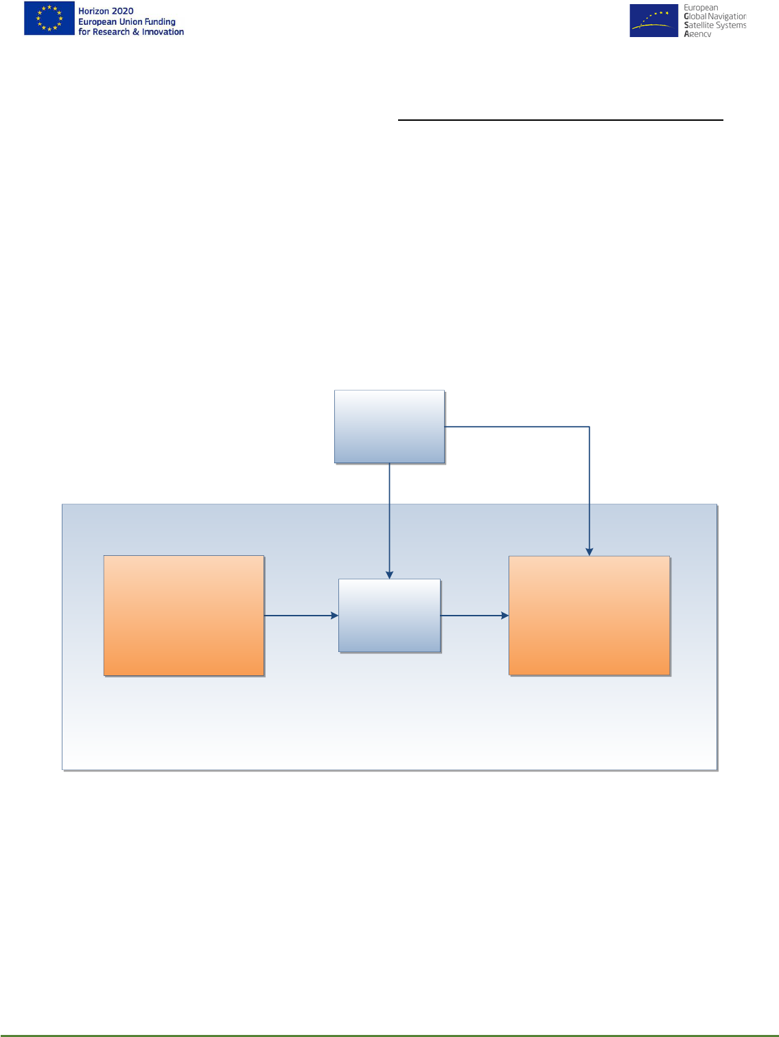
A preliminary concept of the HELMET architecture has been introduced in D2.3 (as shown in Fig. 31
in [2]). If we extract the common essential part of the localization system for all three means of
transportations, the multi-modal positioning and localization system high level architecture is
illustrated in Figure 4. The system contains two main subsystems: Augmentation Integrity Monitoring
Network (AIMN) and Multi-sensor OnBoard Unit (MOBU). The AIMN provides augmentation and
GNSS integrity messages with different service levels based on a network of infrastructures. The
MOBU subsystem is installed on the vehicles for multiple transportation modes, including railways,
automobiles, and UAVs that supports the transportation tasks. A communication module is required
to transmit the messages and services provided by AIMN and application-specific infrastructures to
the MOBU. For different transportation modes, the localization system also exploits additional
application-specific infrastructures, e.g., balise for railway applications and visual markers for road
applications.
Communication
Link
Multi-modal Positioning and Localization System
Augmentation Integrity
Monitoring Network
(AIMN)
Multi-sensor OnBoard
Unit (MOBU)
Application-
specific
Infrastructures
Figure 4: Multi-modal positioning and localization system
The following chapter 4 describes the high level design of the AIMN with the definition of different
service levels. Chapter 5, 6 & 7 describe the high-level architecture for Railway/Automotive & UAV
applications.
HELMET- 870257
Page 18 of 86
D3.1 High-Level Design Document
4. MULTIMODAL AUGMENTATION
INTEGRITY MONITORING
HIGH LEVEL DESIGN
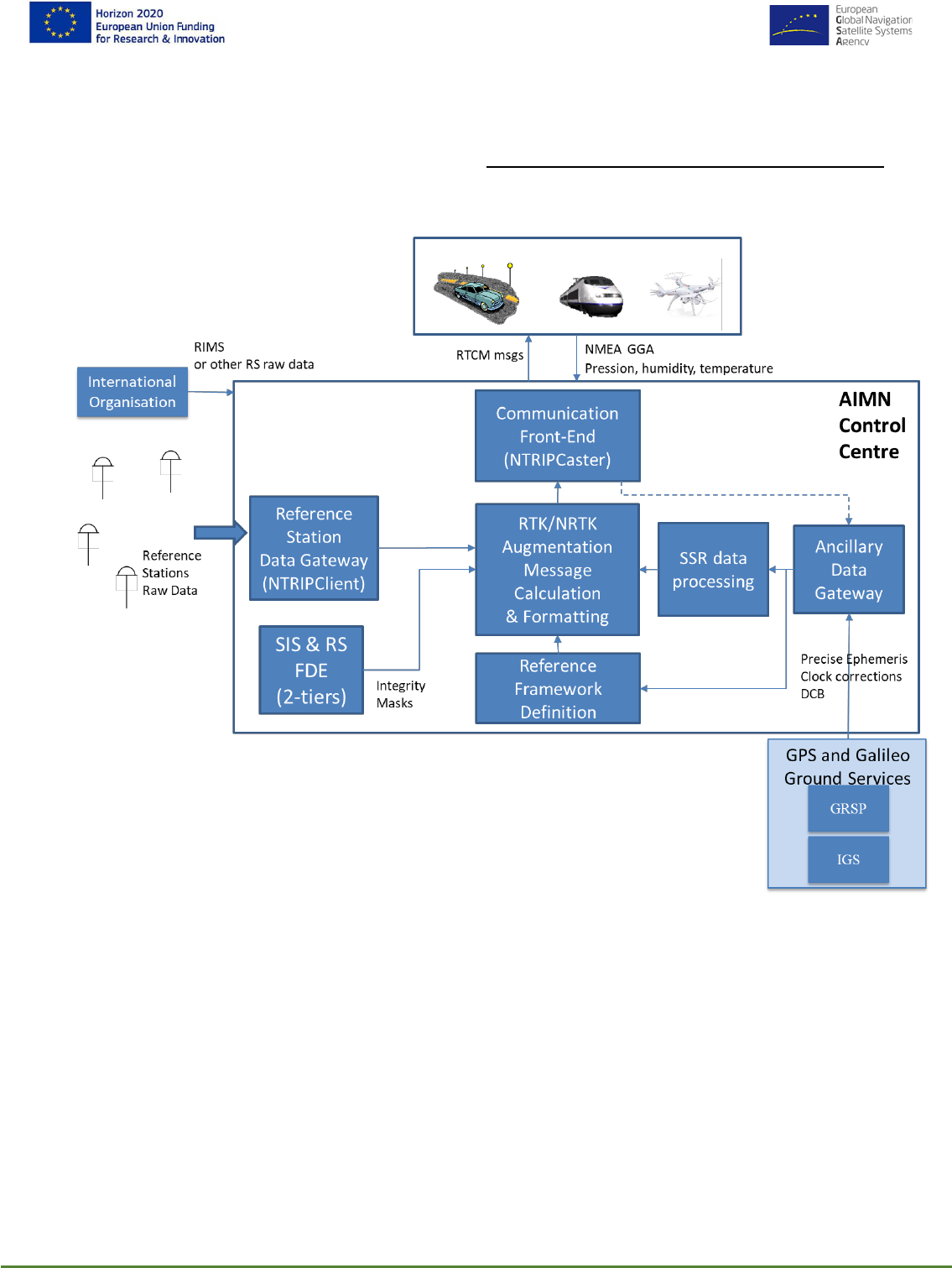
Starting from the high level functional analysis carried out within the D2.3, the Augmentation Network
high level design is represented in Figure 5.
Figure 5: Augmentation Network High Level Design
The AIMN Control Centre take as input the following data:
- International Organisations: International Organisation Reference Stations Raw data can
be used (e.g. EUREF of EDAS RIMS)are used as reference for the implementation of the
first tier of the 2-tiers FDE algorithm
- Reference Stations Raw Data: they are gathered through an NTRIP Client access from
local Augmentation Service providers and are used for the implementation of the second tier
of the 2-tiers algorithm and for the calculation and formatting of the augmentation messages
- GNSS Ground Services: they provide precise ephemeris, clock corrections and differential
code biases needed for the AIMN Reference Framework determination. IGS and the Galileo
Reference Service Provider system are used for GPS and Galileo

HELMET- 870257
Page 19 of 86
D3.1 High-Level Design Document
Users can connect to the AIMN through the single domain Physical Communication system.
Standard NTRIP protocol and RTCM SC-104 formats are used, being it the most implemented
standard for Augmentation data processing into GNSS receivers.
Main subsystems of the Augmentation network and relevant tasks are the following:
- Reference Stations Data Gateway: it implements NTRIP Client access to single Local
Augmentation providers for gathering relevant raw measurements
- Communication Front-End: is an NTRIPCaster publishing mountpoints for the access to
the generated RTCM augmentation messages and the 2-Tiers Integrity masks. It receives
user position for Augmentation Messages calculation
- SIS & RS FDE: the 2-tiers algorithm ([5]), that has been proven to meet SIL-4 THR levels, is
implemented and relevant integrity masks generated for satellites, constellations and
Reference Stations and transmitted to the Augmentation Messages calculation and
formatting for faulted sources exclusion by the user and the network
- RTK/NRTK Augmentation Messages Calculation & Formatting: a quality check on raw
measurements is carried out and RTK messages calculated or Network RTK processing
performed for Reference Stations data generation in the neighbour of the User Receiver
Position. User position id received from the front-end and user for nearest station selection
of NRTK messages generation
- Ancillary Data Gateway: Precise Ephemeris and Clock corrections, Differential Code Biases
and other needed ancillary data are downloaded and used for the Reference Framework
Calculation, errors estimations and SSR parameters gathering from relevant providers.
Tropospheric (e.g. Pressure, Humidity and Temperature) from on the field sensors (e.g. OBU
or Reference Station sensors, if available during the Pilots) can be gathered and processed
for deriving a first level ZTD estimation to be used as a priori information for receivers
estimations. The accuracy of the estimation depends on the quality of the provided data.
Such processing is analysed at functional level, paving the way for a future implementation.
Furthermore, precise Waypoints coordinates (easy detectable by an on board camera, e.g.
Cadastral Fiducial point DB) can be broadcast to the OBU in a suitable format. Such points
can be in a future implementation used by the OBU and merged with angular measurements
for implementing sensor fusion PVT estimations
- SSR Data Processing: basic SR messages (Precise Ephemeris and Clock corrections) are
gathered from external service providers for relevant processing or rebroadcasting. Galileo
HAS corrections messages can be gathered in the same way when transmitted by the Galileo
satellites
Reference Framework Definition: a network adjustment is performed through scientific software
for calculating and updating Reference Stations Coordinates into the ETRF2000 Reference
Framework
AUGMENTATION TO EXTERNAL DOMAIN COMMUNICATION INTERFACES DEFINITION
The Augmentation System Front-End makes available the augmentation messages to the single
domain Communication Front-End (in charge of broadcasting them to the final user) or the OBU in
a widely adopted standard protocol and data format. RTCM is currently the standard format adopted
by the great part of the GNSS receiver manufacturers for the implementation of High Accuracy
Services.

HELMET- 870257
Page 20 of 86
D3.1 High-Level Design Document
Conversion of such Standard to domain specific protocols or formats is in charge of single domain
Communication subsystems or OBU.
5. HIGH LEVEL ARCHITECTURE
FOR RAILWAY APPLICATION
This section deals with the preliminary design of HELMET high-safety integrity LDS architectures for
ERTMS. The preliminary safety design is focused on such LDS solutions to meet user and system
requirements for following functionalities: 1) Track Identification, 2) Odometry calibration, and 3) Cold
Movement Detection. The presented preliminary architectures are designed according to Rail User
Requirement specified in HELMET D2.1 (§4) [1] and Rail System Requirements summarised in
HELMET D2.3 (§5.1 and §7.1) [2].
The first proposed LDS architecture is based on reactive fail-safety with independent diagnosis of
GNSS. The independent GNSS diagnosis utilises ETCS odometry compliant with SIL 4. It is
assumed that LDS initialization including Track Identification has been already performed before
ETCS full supervision started. The main goal of safety analyses performed by Markov modelling is
to demonstrate that the reactive LDS is able to meet THR for the along track position determination
function during nominal train operation (full supervision). Design of key parameters (T
DN
, P
md
, K
md
,
K
fa
, MDE, etc.) of safety monitor/ diagnosis of LDS is outlined. Calculations show that the currently
guaranteed GNSS Integrity Risk for airplane final approach combined with the LDS safety monitor
is able to meet high safety integrity and availability requirements for the ERTMS Virtual balise
concept.
Second, a high-level LDS architecture for Track Identification based on composite safety is
introduced. The composite architecture is intended for LDS initial position determination including
Track Identification during train motion. It is shown that safe LDS initialization can profit not only
from additional on-board sensors for rail infrastructure perception, but also from other external
technical or operational provisions based on track-side data, such as characteristic features of a set
train route (position of switch points) and Movement Authority granted to the train by the Train Control
Centre.
The integral part of the external data is a so called meta data, which characterise the quality of
external LDS data and there are critical for run-time safety evaluation performed by LDS. Fault Tree
Analysis (FTA) demonstrates how significantly can the on-board sensing of infrastructure features
(mainly positions of switches) and external trackside (technical & operational) data contribute to the
reduction of safety requirement for GNSS. Excepting this, efficient experimentally proven on-board
techniques for train routing detection on switches based on gyro-odometry and detection of switch
points elements by a laser sensor developed at Czech Railways in the past have been reminded.
Third, it is briefly analysed what would happen if the above described composite LDS architecture
would be also used for Start of Mission with the LDS status UNKNOWN in stand-still. FTA shows
that unavailability of the rail infrastructure sensing function (composed of several techniques) and
external technical and operational provisions (because they can be only applied during train motion)
significantly increases safety integrity demands on GNSS. It is shown how the above findings could
affect the architecture of Cold Movement Detector (CMD), which is the mandatory constituent of the
ERTMS baseline 3.

HELMET- 870257
Page 21 of 86
D3.1 High-Level Design Document
Finally, based on the proposed high-level safety architectures (ARCHITECTURE_1 and
ARCHITECTURE_2) and performed related safety analyses, the RAIL user and system
requirements were converted to the subsystem level.
5.1 RAILWAY PRINCIPLES USED FOR SAFE
ARCHITECTURE DESIGN
Railway safety related systems to be compliant with SIL 3 or SIL 4 must ensure that they will remain
safe in the event of any kind of single random HW fault. This principle is known as fail-safety and
can be achieved by means of the following techniques [3]:
• inherent fail-safety,
• composite fail-safety, or
• reactive fail-safety.
Figure 6. Fail-safe techniques according to CENELEC: (a) composite fail-safety, and (b) reactive fail-safety.
It is evident that implementation of these techniques not only determines which level of safety can
be achieved in the Virtual Balise Reader (VBR) based on GNSS SoL service, but also how efficiently
the GNSS service may be used. The applicability of the individual fail-safety techniques within the
GNSS -based VBR is analysed below.
The inherent fail-safety technique allows a safety-related function to be performed by a single
channel, provided that all the credible failure modes of the channel are not hazardous. It would be
very difficult or impossible to make such evidence in the case of the complex GNSS + VBR, and
therefore inherent fail-safety is not further considered.
The composite fail-safety (Figure 6(a)) allows a safety-related function to be performed by at least
two independent channels. A hazardous fault in one channel shall be detected and negated in
sufficient time to meet the required THR. The fault is detected by the comparison of the output values
of these two or more channels, or also by means of an additional independent diagnosis. This
technique can be applied if two fully equivalent and diverse safety functions exist. Application of this
technique is investigated in case of Track Identification function below.
Finally, the reactive fail-safety (Figure 6(b)) allows a safety-related function to be performed by a
single channel, provided its safe operation is assured by fast detection and negation of any
dangerous fault. For example, legacy SBAS (Satellite Based Augmentation System) or GBAS
(Ground Based Augmentation System) itself can be considered as a system with reactive fail-safety,

HELMET- 870257
Page 22 of 86
D3.1 High-Level Design Document
because the safety function (i.e. position determination) is performed by the GNSS constellation(s)
and its correctness is checked by the SBAS/ GBAS infrastructure.
5.2 ARCHITECTURE_1: REACTIVE FAIL-SAFETY
FOR ALONG TRACK TRAIN POSITION
DETERMINATION
This section deals with the preliminary reactive Location Determination System (LDS) architecture
intended for Virtual Balise (VB) detection, Cold Movement Detection (CMD) and Odometry
Calibration.
Position determination along track is a position estimation problem. In this case, it is possible to
define a FAIL-SAFE STATE when a hazardous failure arises – i.e. train can stop, slow-down, etc.
Therefore, the reduction of Time to Fault Detection and Negation (T
DN
), which correspond to Safe
Down Time (SDT) according to EN 50129 [3], can enable a significant reduction of safety
requirements (i.e. THR increasing) for subsystems such as GNSS and independent diagnosis –
see Figure 6.
In composite solution (Figure 6(a)) the independent diagnosis can be performed by comparing two
full-value diverse safety functions (A and B). In this case it is considered that both Function A and
Function B provide absolutes independent position determination.
Reactive fail-safety in Figure 6(b) is in fact a modification of the composite solution, because an
independent diagnosis (i.e. fault detection) of Function A must be performed. In case of reactive
safety there is only required that the independent diagnosis must detect and negate promptly enough
all failures, which could bring the system into a hazardous state.
The reactive LDS architecture was selected to implement the along track GNSS-based safe
positioning function. The reduction of railway safety requirements for GNSS SoL service, i.e.
exploitation of existing aviation EGNOS SoL service, and use of already available ETCS odometry
(SIL 4 compliant) are the main reasons why the reactive solution is proposed for along track train
position determination. It means that reactive fail-safety is achieved by combination of absolute
position determination (GNSS) and relative positioning (odometry). It is the major difference with
respect to composite fail-safety applied for along track positioning (ATP), which is considered to be
realised by two diverse absolute position determination functions. Since excepting GNSS no other
efficient absolute positioning technology is available, therefore the reactive LDS architecture with a
fail-safe state based on GNSS and odometry was proposed in sections below.
5.2.1 Markov model of reactive LDS
A possible high-level reactive LDS architecture solution (Architecture_1) based on GNSS + AIMN +
ETCS odometry including its Markov model is outlined in Figure 7 [4]. Reactive fail-safety is based
on the principle that the first single failure which could be hazardous, i.e. an excessive along-track
position (ATP) error, either alone or if combined with a second failure, shall be detected and a safe
state of the system enforced (i.e. failure negated) to meet the specified quantified safety target
(THR
H7
of 3.3e-10/h – Virtual Balise insertion along track [2]). Note that THR
H7
is in fact a hazard
related to virtual balise detection, not specifically the output of the LDS for which the hazard is that

HELMET- 870257
Page 23 of 86
D3.1 High-Level Design Document
the ATPL (Along Track Protection Level) does not bound the ATP error. For simplification, however,
THR
H7
is referred to as the safety target in this section.
Figure 7: Reactive LDS safety structure based on HELMET AIMN and independent diagnosis, including Markov model
Time to failure detection and negation (T
DN
), which is a critical parameter of the reactive architecture,
can be derived using the above Markov model – see Figure 7 on the right. T
DN
is also called Safe
Down Time (SDT) according to EN 50129.
The following four system states are defined for the model:
• S
0
: Fully functional LDS state: both ATP (Along Track Positioning) and independent diagnosis
work well according to the specifications. The corresponding probability P
0
(t) represents
probability of correct LDS functioning;
• S
1
: Safe faulty LDS state: ATP is faulty (out if specifications) and rapid diagnosis is functional.
This represents the state of the system prior to T
DN
elapsing. The state is characterised by
the tolerated LDS faulty state probability P
1
(t) that directly depends on T
DN
. Note: If the
faulty sate probability is tolerated, then it means safe (faulty) state;
• S
2
: Fail-safe state of the LDS: ATP fault was detected and negated within T
DN
. The
corresponding probability P
2
(t) represents LDS failure probability in the absorbing state;
• S
3
: Hazardous LDS state, i.e. dangerous undetected failure mode: Independent diagnosis of
ATP did not detect the fault. Note: although LDS can function properly according to the
specifications, the LDS is in a dangerous state. The corresponding probability P
3
(t)
represents probability of dangerous undetected LDS failure in the absorbing state.
A set of first-order differential equations with constant coefficients describing the Markov model in
Figure 7 is following:
= -

HELMET- 870257
Page 24 of 86
D3.1 High-Level Design Document
=
–
(1)
=
=
Boundary conditions are following: P
0
(0)=1, P
1
(0)=0, P
2
(0)=0, P
3
(0)=0 .
5.2.2 Derivation of Time to Fault Detection and Negation
The corresponding time-dependent LDS state probabilities derived from the set of differential
equations (1) are followings:
(2)
(3)
(4)
(5)
Where, HR
GNSS MI
is hazard rate per 1 hour of GNSS+AIMN-based ATP determination, HR
Diag
is
hazard rate of independent GNSS diagnosis, µ is rate of fault detection and negation, i.e. µ
=1/T
DN
=1/SDT.
P
0
(t) represents LDS reliability, i.e. when both GNSS and independent diagnosis are functioning
correctly. It includes only one successful LDS state – S
0
. The other system states (S
1
,
S
2
, S
3
) are
faulty states – safe states (S
1
,
S
2
) or dangerous state (S
3
). State S
3
is the most feared sate, i.e.
dangerous undetected fault.
States S
2
and S
3
are absorbing states. An absorbing state means that model ends in this state. Since
in this reactive LDS architecture we assume that T
DN
is very short (with respect to Mean Time to
Failure (MTTF) of the other channel, i.e. 1/ HR
GNSS MI
), then we can say that S
1
is practically also an
absorbing state, because the P
3
(t) is very low (negligible).

HELMET- 870257
Page 25 of 86
D3.1 High-Level Design Document
Hazard rate of the system (
system
) is generally calculated using failure probability density f(t) and
reliability R(t) as follows:
(6)
However, R(t) is calculated using state probabilities for non-absorbing states. It means that we
cannot calculate R(t) which would also include probabilities for absorbing states S
1
and S
2
.
Therefore, we had to find another solution.
P
1
(t) is the safe faulty state probability of LDS in case of GNSS+AIMN-based ATP fault. Then the
tolerated (expected) probability P
1
(t) for a given value of T
DN
over next interval of 1 hour characterizes
integrity of the safe faulty state S
1
. The expected LDS failure probability P
1
(t) during next 1 hour
interval for T
DN
can be used instead of HR.
Since (HR
GNSS MI
+ HR
Diag
) is much smaller than µ, then equation (3) can be simplified as follows:
(7)
It is evident from equation (7) that P
1
(t) depends on T
DN
(i.e. on 1/ µ) and is no longer dependent on
the time t – see Figure 8. The required THR for LDS during one hour long mission can be expressed
as THR
req
= P1 per 1 hour = HR
GNSS MI
× T
DN
× 1 hour
-1
. Then the T
DN
can be calculated as:
Figure 8: Probability of failure as a function of HR
Non-Train(SIS)
and T
DN

HELMET- 870257
Page 26 of 86
D3.1 High-Level Design Document
Failure of ATP determination (by GNSS) at the LDS system level must not bring the system into a
dangerous state. The safe faulty state (P
1
) of the LDS system in case of ATP failure when the
independent diagnosis is functional has a duration of T
DN
at most because the value of T
DN
is
designed in such a way that the LDS meets the required THR
req
– i.e. THR
H7
of 3.3e-10/h. In other
words, the reactive LDS will be in a safe state although ATP has failed. If ATP failure has not been
detected and negated within T
DN
, then the LDS state is considered as hazardous. An ATP failure
due to GNSS MI cannot be considered as the TPL hazard. It can be only considered as cause of
TPL hazard because the independent diagnostic channel (i.e. Safety Monitor) exists.
The parameters of the diagnostic channel, also called safety monitor, are derived below.
5.2.3 Numerical verification of meaning of LDS state probabilities
Example_1:
Let’s assume HR
GNSS MI
= 7.5e-06/ hour (see §4.1.5 in [2]), HR
Diag
= 1e-10/ hour (example taken for
ETCS odometry), T
DN
= 4.4e-05 h (0.158 s), t=1 hr
Results:
P0 = 0.999992499928126
P1 = 3.299975250851821e-10 …. i.e. THR
H7
of 3.3e-10/h is met
P2 = 7.499641877184870e-06
P3 = 9.999962499759281e-11
Example_2
Let’s assume HR
GNSS MI
= 7.5e-06/ hour, HR
Diag
= 1e-10/ hour, T
DN
= 4.4e-05 h (0.158 s), t=100 hrs
Results:
P0 = 0.999250271187198
P1 = 3.297525896005952e-10 …. i.e. THR
H7
of 3.3e-10/h is met
P2 = 7.497184867985195e-04
P3 = 9.996250887349615e-09
Example_3
Let’s assume HR
GNSS MI
= 7.5e-06/ hour, HR
Diag
= 1e-10/ hour, T
DN
= 2.77e-3 hour (10 s), t=1 hr
Results:
P0 = 0.999992499928126
P1 = 2.083317751586627e-08 …. i.e. THR
H7
is not met for T
DN
= 10 s
P2 = 7.479138697198274e-06
P3 = 9.999962499759281e-11
Conclusions from Examples_1 to 3:
HELMET- 870257
Page 27 of 86
D3.1 High-Level Design Document
• Probability P0 corresponds to reliability. It is evident it is time dependent.
• Probability P1 doesn’t depend on time t. It depends on T
DN
. It is evident that required THR
H7
of 3.3e-10/ h can be met for T
DN
= 4.4e-05 h = 0.158 s (Example_2). If T
DN
is longer, e.g. 10
s (i.e. 2.77e-3 hour), then P1 = 2.083317751586627e-08 over 1 hour interval doesn’t meet
the required THR
H7
of 3.3e-10/ h (Example_3).
• Probabilities P2 and P3 depend on time t (Example_1 and Example_2). It is natural that. But
it doesn’t have a practical relevance. It is because P2 represents a fault probability after fault
was negated – no hazard can happen in the state S
2
. P3 represents dangerous undetected
fault probability of independent diagnosis, which is latent in any case.
5.2.4 Interpretation of T
DN
as P
md
The above described time dependency having impact on resulting THR cannot be directly modelled
by means of an FTA diagram. Therefore, the above reactive technique depicted in Figure 7 can be
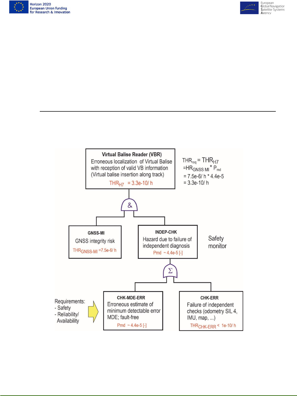
redrawn using Fig. 38 in HELMET D2.3 [2] as it is outlined in Figure 9:
Figure 9: Safety monitor in FTA diagram.
The derived Time to Failure Detection and Negation T
DN
can be interpreted in the FTA in Figure 9
via the Probability of Missed Detection (P
md
). Interpretation of T
DN
as P
md
is explained below in §
5.2.8 .

HELMET- 870257
Page 28 of 86
D3.1 High-Level Design Document
5.2.5 Proposed Safety Monitor for run-time safety evaluation
The principle of the safety monitor to be developed for the reactive LDS architecture is outlined in
Figure 10. It evaluates difference in travelled distance measured by GNSS-based LDS and safe
ETCS odometry (SIL 4). If the position error exceeds the Maximum Threshold T
max
(defined by user,
T
max
≥ MDE), then the GNSS ATP failure is detected and negated.
Figure 10: Determination of Minimum Detectable Error (MDE) and maximal decision Threshold T
max
5.2.6 Steps in Safety Monitor design
Design of safety monitor of reactive LDS consists of following steps:
i. Determination of safe down time (T
DN
) using THR
req
and HR
GNSS MI
T
DN
= T
D
(Time to failure Detection) + T
N
(Time to failure Negation);
ii. Determination of missed detection probability (P
md
), which corresponds to the ratio of T
DN
/ 1
hour;
iii. Derivation of probability of false alert P
fa
from the required LDS availability;
iv. Derivation of scaling coefficients K
md
and K
fa
of the safety monitor;
v. Determination of Minimum Detectable Error (MDE) of safety monitor.

HELMET- 870257
Page 29 of 86
D3.1 High-Level Design Document
5.2.7 Example: Derivation of time to failure detection and negation (T
DN
)
Based on Figure 39 in HELMET D2.3 [2], the following assumptions may be made:
• HR
GNSS MI
= 7.5e-6 / hour, which
includes Ground segment fault free system Integrity Risk
(FAULT-FREE), Integrity Risk due to Signal-In-Space Misleading Information (SIS-MI) and
Integrity Risk due to user MI (USER-MI);
• THR
req
=THR
H7
= 3.3e-10 / hour (Virtual Balise insertion along track);
Then time to failure detection and negation T
DN
may be calculated according to:
This gives T
DN
= 3.3e-10 / 7.5e-6 x 1 hour = 4.4e-5 x 1 hour = 0.158 s.
5.2.8 Example: Determination of P
md
for GNSS+AIMN-based ATP failure
Figure 11: Determination of P
md
from duration of GNSS+AIMN-based ATP failure T
DN
Safe down time T
DN
represents the time interval during which the LDS (GNSS+AIMN + independent
diagnosis) is in safe state and also remains safe after output switch was disconnected – see Figure
11 and Figure 7. Since it is assumed that the GNSS+AIMN-based ATP dangerous failure can appear

HELMET- 870257
Page 30 of 86
D3.1 High-Level Design Document
during the next 1 hour time interval with a certain probability, then the T
DN
[hr] relative to 1 hour
represents acceptable Probability of missed detection P
md
, for which the system still remains safe
with regard to the required level THR
req
. The probability P
md
= T
DN
/ 1 hour [-] represents one of the
basic parameters of independent diagnosis, i.e. safety monitor.
P
fa
- is derived from the required LDS availability A defined using unavailability (of ETCS on-board
equipment) U= 1- A= P
fa
. The Gaussian distribution is employed in the safety monitor – see Figure
10. The K
md
and K
fa
coefficients are determined as follows:
5.2.9 Example: MDE determination
Let us assume as an example that LDS unavailability for ERTMS OBU should be U=1e-6, as it is
defined in HELMET D2.3 [2]. Then availability is A= 1-U = 0.999999. If MTTR (Mean Time to Repair)
=1 hour, MDT(Mean Down Time) for ETCS OBU is 1 hour, then MTBF (Mean Time Between
Failures) is about 1e6 hours. Probability of false alert during 1 hour mission is P
fa
= 1/MTBF * 1hour
= 1.0e-6 [-]. Correlation in the monitored travelled distance error is omitted due to diversity between
GNSS and odometry sensors. Further let us assume that P
md
= 4.4e-5 [-] (derived above). Then
• K
fa
(along track) = Norminv (1 - 1.0e-6/2, 0, 1) = 4.8916 ≈ 4.90
• K
md
(along track) = Norminv (1 - 4.4e-5, 0, 1) = 3.9214 ≈3.92
Let’s assume that 1-sigma of position accuracy along track (
ATP
) is about 1.5 m for SBAS and
odometry error is omitted for short travelled distance. Then MDE can be estimated as
MDE = K
fa
x
test|ff
+ K
md
x
test|faulty
MDE ≈ (K
fa
+ K
md
) x
ATP
= (4.90 + 3.92) x 1.5 = 8.82 x 1.5 = 13.23 m ≈ 14 m
Let’s assume that 1-sigma of position accuracy along track (
ATP
) could be about 0.1 m for HELMET
solution supported by AIMN, then
MDE ≈ (K
fa
+ K
md
) x
ATP
= (4.90 + 3.92) x 0.1 = 8.82 x 0.1 = 0.882 m < 1 m
In this case MDE would meet requirement for the location accuracy (of on-board ERTMS Balise
Transmission Module – BTM), which shall be within ±1 m for each (physical) balise, when a balise
has been passed [5]. In this case HELMET solution would meet the requirement for the Odometry
calibration function.

HELMET- 870257
Page 31 of 86
D3.1 High-Level Design Document
Maximal decision threshold T
max
can be set to e.g. 20 m due to operational reasons (to further
improve LDS availability).
5.3 ARCHITECTURE_2: COMPOSITE SAFETY FOR TRACK
IDENTIFICATION
Track discrimination required for ERTMS Start of Mission (SOM) with UNKNOWN status (train
position is not a priory known) is a decision problem. In this case it is not possible to define a FAIL-
SAFE STATE from the system design point of view, which could help to reduce (via fast diagnosis)
safety requirements for subsystems (GNSS and independent diagnosis) and simultaneously meet
required THR (FFR). We cannot say that the determined position of train on one track is safer than
on the other one. A fast diagnosis used in the above Position Estimation Problem is not applicable
for Track Identification / discrimination. It would be wrong to say that fast diagnosis reduces the
system FFR (Functional Failure Rate) in this case. If we would (incorrectly) accept this possibility,
then THR of 3.3e-10/ h required for track discrimination/ identification could be theoretically met (see
HELMET D2.3, §4.1.4, eqn (1) ) by low quality functions A and B (let’s say FR
A
= FR
B
=1e-2/ h) if
SDT would be very short, i.e. 3.3e-6 hour = 0.01188 s - and it is a nonsense.
It is assumed that Track Identification function in LDS status UNKNOWN is performed in Staff
Responsible (SR) mode with a defined low ceiling speed (e.g. v < 30 km/h). It means that safety of
moving train during execution of Track Identification function is under responsibility of driver. If LDS
failure is detected, it means that Track Identification was not successfully completed. Dangerous
undetected failure of Track Identification function has no impact on railway safety in SR mode.
However, this latent LDS failure can have hazardous consequences in subsequent normal train
operation (full supervision of ETCS). Therefore, derivation of (hazardous) Functional Failure Rate
(FFR) of Track Identification function is derived below.
Since fast LDS diagnosis during SR mode has no impact on railway safety, then LDS can be
modelled in a simplified way as a system without failure detection mechanisms. Note: In reality, the
LDS will obviously have a failure detection mechanism to notify that the Track Identification function
has not been successfully completed. The corresponding Markov model of two-channel LDS (two-
out-of-two) performing Track Identification function is shown in Figure 12.

HELMET- 870257
Page 32 of 86
D3.1 High-Level Design Document
Figure 12: Markov model of two- channel LDS (2oo2) without failure detection
The following four system states are defined for the model:
• S
0
: Fully functional LDS state at time t=0;
• S
1
: Element A has a failure - safe faulty state in SR mode;
• S
2
: Element B has a failure - safe faulty state in SR mode;
• S
3
: Both elements have failure Hazardous LDS state – it is dangerous undetected failure
mode. The corresponding probability P
3
(t) represents probability of hazardous latent
failure. This latent failure can endanger railway safety in ETCS full supervision mode.
Solution of liner differential equations of Markov model gives probability P
3
(t) as
Since P
3
(t) corresponds to FFR * t, then for next 1 hour interval one can write
It is evident that realization of the Track Identification function using composite safety requires higher
demands on subsystems (A, B) from viewpoint of safety integrity. For example, the THR requirement
of 3.3e-10/ h for track discrimination function can be met by GNSS position determination as a
Function A with FR
A
of 1e-6/ h and independent diagnosis of GNSS as a Function B with FR
B
of 1e-
4/ h. In this case FFR
Track discrimination
equals to 1e-10/ h.
In case of Along Track Position (ATP) estimation, the THR requirement of 3.3e-10/ h can be met
e.g. by GNSS as a Function A with FR
A
of 1e-4/ h and independent diagnosis of GNSS as a Function

HELMET- 870257
Page 33 of 86
D3.1 High-Level Design Document
B (also absolute position determination) with FR
B
of 5e-3/ h and SDT of 1 s. It can be calculated
using
as stated in [3] and §4.1.4 of HELMET D2.3 [2]. Then FFR
Position estimation
equals to 2.7778e-10/ h.
Duration of track discrimination is limited by operational reasons – i.e. by the average duration of
Start of Mission in Staff Responsible, which is 3% of mission duration (1 hour) according to the
SUBSET-088 [6], i.e. 108 seconds. However, this operational parameter has no impact on safety
integrity of the proposed system architecture.
ETCS onboard subsystem shall take no more than 60 s to go from No Power (NP) to being ready to
accept data entry in Standby (SB) [11]. Therefore, values of 10s < TTA < 30 s proposed by the
HELMET User Requirement UR_001 [1] is appropriate.
5.3.1 Rules for realization of safety related functions with
TFFR < 1e-9/ hour (EN 50129, IEC 61508)
The quantitative safety requirement for Track Identification is expressed through THR
H9
of 3.3e-10/
hour which is related to erroneous reporting of Virtual Balise in a different track – see HELMET D2.3,
Figure 34 [2]. In this development stage, this requirement can be also considered as THR
requirement for across track train position determination function.
According to EN 50129, a safety-related function having quantitative requirements more demanding
(lower) than 1e-9/h shall be treated in one of the following ways:
• if it is possible to divide the function into functionally independent sub-functions, the TFFR
can be apportioned between those sub-functions (allocating TFFR to these functions) and a
SIL allocated to each of them;
• if the function cannot be divided, the measures and methods required for SIL 4 shall, at least,
be fulfilled and the function shall be used in combination with other technical or operational
measures in order to achieve the necessary TFFR.
Similarly, IEC 61508-1 sets a lower limit on the target failure measures for a safety function carried
out by a single E/E/PE safety-related system. For E/E/PE safety-related systems operating in a high
demand or a continuous mode of operation, the lower limit is set at an average frequency of a
dangerous failure of 1e-9/ hour.
Conclusion: Track Identification function for ERTMS with based on GNSS must not be realised as a
single function.
5.3.2 AND-combination logic
Railway functional safety is strictly based on logical AND-combination approach, i.e. failure of
functions shall be independent with respect to systematic and random faults. Independence among
functions, from common random causes (CCF) and common systematic causes is required.

HELMET- 870257
Page 34 of 86
D3.1 High-Level Design Document
When a hazard results from the failure of two or more independent functions (i.e. logical AND combinations),
the following rules shall be applied (EN 50129 [3]):
• Freedom from common random and systematic causes shall be demonstrated by CCF analysis;
• Each function shall be able to prevent the hazard. Therefore, a failure of one of the independent
functions shall not lead to the hazard (i.e. fail-safe approach must be implemented);
• The functions shall be diverse (i.e. use different functional approaches or technology) so as to avoid
common causes leading to the hazard;
• Safety integrity of each independent function shall not rely on the results (e.g. outputs) of the other
independent function(s).
• A fault in any function shall be detected and a safe state enforced within a time compatible with the
THR/TFFR of higher level hazard or function. This detection should be provided by a means
independent of the function under consideration.
Note: In case of Track Identification function (LDS status UNKNOWN), time to failure detection and negation
T
DN
doesn’t impact safety integrity of LDS. Track Identification is a decision problem without a priory defined
a fail-safe state (track number). Track Identification (LDS status UNKNOWN) is being performed in Staff
Responsible (SR) mode with low ceiling speed (v< 30 km/hr), so railway safety in this mode is under train
driver’s responsibility.
5.3.3 High-level composite LDS architecture for Track Identification
based on track-side data
In this section there is proposed LDS architecture with composite safety (ARCHITECTURE_2) that
profits from competitive technical and operational data (including relevant meta data) provided by
the railway track-side infrastructure and Traffic Control Centre. The safety-related track-side data
and relevant meta-data are aggregated for a pre-set train route before Movement Authority is granted
to the train driver. The on-board LDS sensor data are then AND-combined with the diverse track-
side data (and meta-data) in order to improve LDS safety integrity. In addition to Track Identification,
this architecture is also intended for along track position determination. The proposed composite
LDS architecture is outlined in Figure 13.

HELMET- 870257
Page 35 of 86
D3.1 High-Level Design Document
Figure 13: Principal composite safety LDS architecture intended for Track Identification function
In contrast to road transport, railway vehicles cannot arbitrarily move on the railway infrastructure. A
Movement Authority must be granted to a specific train / driver. Before the MA is sent to the train, it
must be known where the train has to go (track number, location) and which route the train will run
on. It is evident that the operational information rated to MA and technical information regarding train
route setting could be utilized for LDS safety improvement. It means that in addition to functional
safety principles (used for GNSS-based LDS) also other safety provisions such as Technical
measures or Operational measures can significantly improve safety integrity of train position
determination function, if they could be logically combined via AND operator – see Figure 14.

HELMET- 870257
Page 36 of 86
D3.1 High-Level Design Document
Figure 14: FTA of the LDS with composite safety: technical and operational safety measures have been introduced to
meet the required THR < 1e-9/ hr for main LDS hazard.
In addition of train position determination using GNSS + ARAIM, movement of train on the railway
infrastructure could be determined via on-board environment sensing techniques such as gyro-
odometry, computer vision, detection of rail switch elements (e.g. guard-rail), etc.
Further, diagnostic data coming from railway infrastructure (e.g. switch position monitored via switch
position sensor device) supporting LDS integrity enhancement can be used as Technical safety
measures. And finally the information regarding MA provided by a Traffic Control Centre could be
utilized as Operational safety measures – see Figure 15.

HELMET- 870257
Page 37 of 86
D3.1 High-Level Design Document
Figure 15: FTA of LDS with applied specific technical and operational safety measures. Examples of minimum THR/TFFR
requirements for individual functions in the composite solution are marked in red)

HELMET- 870257
Page 38 of 86
D3.1 High-Level Design Document
5.3.4 Rail track-side infrastructure sensing
Train routing detection on rail switch points can be efficiently based on measurement of train
movement direction by gyroscopes. Problem is that gyros suffers by drift and therefore this technique
can be usually used for speeds above about 10 km/ hr. For speeds less than 10 km/ h another
technique should be used.
In sections below there are remembered two (rail environment) sensing techniques, which were
developed and successfully tested at Czech Railways around year 2000. These techniques are:
• Train routing detection on switch point based on gyro-odometry and Bayes theorem.
• Detection of guard rails of switch point using laser sensor.
Train routing detection on switch point based on gyro-odometry and Bayes theorem [7]-[9]
The probabilistic safety qualification method presented in this paragraph is based on knowledge of
the precise reference trajectory and gyro-odometry data during movement of a train on the track or
switch. This method requires statistical independence of the measured heading data which has been
already experimentally demonstrated and described in [8].
Note (year 2020): The statistical independence of heading data measurement can be assured from
today’s point of view by using several diverse gyros, since these MEMS sensors are very cheap
now.
The differences between two successive heading measurements and the travelled distance data
provided by an odometer can be used for train trajectory calculation (dead reckoning) from the known
initial point. However, these heading differences are still influenced by a drift of the gyro, which
introduces an error in the computed trajectory. In order to compensate the gyro drift effect on decision
making on a switch, the double heading differences (DHD) have been introduced with an aid of the
precise reference track axis map [8], [9].
.)()()(
and )()()(
where)()()(
___
_
,
tttt
tttt
ttt
nrefnrefnref
measmeasmeas
nrefmeasn
−=
−=
−=
−
−
(8)

HELMET- 870257
Page 39 of 86
D3.1 High-Level Design Document
(a) (b)
Figure 16: Train routing detection on switch by means of gyro-odometry: (a) based on double heading differences (DHDs),
and (b) complementary diagrams of heading differences for ride in deflecting direction (above) and in straight direction .
The double heading difference δ
n
(t)
according to eqn. (8) means the difference between the
measured heading difference Δφ
meas
(t) of the vehicle and the corresponding heading difference
Δφ
ref_n
(t) computed from the precise n-th reference trajectory, where Δt is a time interval
between two heading measurements. Obviously, the consistency of the measured and the calculated
heading differences on the switch mainly depends on the accuracy of travelled distance
measurement.
The principle of train routing detection on the switch by means of double heading differences is
outlined in Figure 16. Figure 16 (a) shows that DHD propagate along both reference trajectories
depending on the distance travelled. DHD are used for decision making on which of tracks the train
is located during passing the switch. A characteristic dependence of heading differences obtained
from heading measurement by gyro(s), and calculated heading differences from the reference
trajectories (Track_1 and Track_2) on travelled distance for ride in deflecting (above) and straight
directions are shown in Figure 16 (b). DHD are calculated using the measured and calculated
heading differences (8).
The decision process evaluating train routing detection on a switch is based on the conditional
probabilities and Bayes’ theorem (9) [8], [9]:
)|()()|()(
)|()(
)|
2211
11
1
(
HAPHPHAPHP
HAPHP
AHP
+
=
(9)

HELMET- 870257
Page 40 of 86
D3.1 High-Level Design Document
H
1
and H
2
are two inconsistent hypotheses. The hypotheses H
1
and H
2
mean that the train is
located on the tracks No. 1 and No. 2, respectively. The term P(H
1
) is the prior probability (known
before measurement) that the train is located on the track No. 1. The term P(H
2
) means the same
but for the track No. 2. Before the decision process of routing detection begins (the first axle of a
vehicle is located on the blade of the switch), the prior probabilities P(H
1
) and P(H
2
) equal 0.5 . The
term P(A| H
1
) means the conditional probability that the train is located on the track No. 1 after the
experiment A, i.e. heading and distance travelled measurements were performed. The term P(A| H
2
)
is the same conditional probability for the track No. 2. The conditional probabilities P(A| H
1
) and P(A|
H
2
) can be expressed by means of the successive double heading differences (8) as follows
||||
||
)|(
||||
||
)|(
)()(
)(
)()(
)(
21
1
2
2
2
1
1
tt
t
tt
t
HAP
HAP
+
=
+
=
(10)
Finally, the posterior probability P(H
1
|A) that the train is located on the track No. 1 is derived in eqn.
(11).
||)(||)(
||)(
)|(
)()(
)(
1
2
2
1
2
1
1
tt
t
HPHP
HP
AHP
+
=
(11)
According to (11), the resulting probability evaluating routing detection on the switch can be
computed from the heading data and the instant position of the train in the route map determined by
means of the odometric data. In each following step, the computed conditional probabilities (10)
replace P(H
1
) and P(H
2
), respectively. The error of the odometer taken as a parameter enables
investigation of the relation between the odometric error and the final posterior probability computed
by means of eqn. (11).
Sensor data validation during train routing on the switch
A diagram in Figure 17 shows the relation among the heading differences and the travelled distance
within the routing detection experiment. The data was recorded on the switch with the crossing
angle of 7
46‘03‘‘ at speed of 40 km/hour.
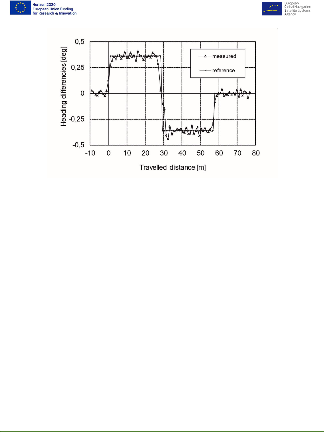
HELMET- 870257
Page 41 of 86
D3.1 High-Level Design Document
Figure 17: Heading differences vs. travelled distance on the switch
The locomotive was passing the switch in the diverging route. Zero value on the travelled distance
axis in this and the next diagram means the front of the switch blade. From this diagram is evident
that the heading differences measured by the KVH FOG and the reference heading differences
computed by means of the precise map match well. If the measured double heading differences do
not match with the computed ones, a fault of gyroscope is indicated.
Train routing detection experiments on the switch
The same odo-gyro data was employed for evaluation of the routing detection process by means of
the conditional probabilities and Bayes’ theorem according to the eqn. (9) – (10). A diagram in Figure
18 shows three computed probabilities P(H
1
|A) of routing vs. travelled distance on the switch for
the following error modes of the odometer: a) the real recorded odometric data – i.e. without an
error, b) the intentionally introduced error of 2.5 meters and c) the intentionally introduced error of 5
meters. According to the error mode a) the probability P(H
1
|A) achieved value of 0.99999 after the
locomotive travelled a distance of 11.7 meters from the front of switch blade. The same levels in
modes b) and c) were achieved for the travelled distances of 13.9 and 17.4 meters, respectively.
These results confirm the fact the routing decision process depends on the performance of odometric
system. Since the distance between the front of the switch blade and the frog is 21.8 m, the above

HELMET- 870257
Page 42 of 86
D3.1 High-Level Design Document
Figure 18: The posterior probability P(H
1
|A) of the routing detection vs. travelled distance on the switch
specified probability level is achieved before the train arrives to the frog. Therefore, the odometric
error of +/- 5 meters seems also acceptable for the routing decision process. This method is simple,
low cost and efficient.
Detection of characteristic switch elements using laser sensor
Many of railway switch points are equipped by a guard rail (check rail). It is a short piece of rail placed
alongside the main (stock) rail opposite the frog – see Figure 19. These ensure that the wheels follow
the appropriate flangeway through the frog and that the train does not derail. Generally, there are
two of these for each frog, one by each outer rail.
Figure 19. Fundamental elements of rail switch [12]
Guard (Check) rails can be detected by on-board equipment in order to get an additional indication
if the train pass the switch in divergent route / turnout or through route - see Figure 20.

HELMET- 870257
Page 43 of 86
D3.1 High-Level Design Document
Figure 20: Detection of guard rail to get information on train routing
Guard rails are not required with a "self-guarding cast manganese" frog, as the raised parts of the
casting serve the same purpose – see Figure 21 .
Figure 21: Switch with "self-guarding cast manganese" frog without guard rails [13]
Guard rails are not installed on a switch with movable point frog as well – see Figure 22.

HELMET- 870257
Page 44 of 86
D3.1 High-Level Design Document
Figure 22: Switch with movable frog without guard rails [14], [15]
Detection of guard rails using laser sensor was designed as a competitive technique to increase
safety integrity of train routing detection on switch. The principle is outline in Figure 23.
Figure 23: Principle of guard rail detection using laser sensor – works well in snow on track (tested in operations)
This principle was developed and tested at Czech Railways around year 2000. The advantage of
the principle consists in fact that it works very well in snow because a wheel clean space between

HELMET- 870257
Page 45 of 86
D3.1 High-Level Design Document
rail and guard-rail (~ 40 mm). It works well in the speed range 0-80 km/ hour. This technique has
been successfully used on railway infrastructure diagnostic vehicles.
In cases when guard rail is not installed, characteristic switch features can be detected e.g. by
computer vision.
At Czech Railways field tests focused on detection of guard-rail by inductive proximity sensors were
also performed in the period of 2000-2003 – see Figure 24.
Figure 24: Detection of guard rail using inductive proximity sensor
However, application of such inductive sensors was found inefficient, because these sensors usually
work with quite short distance between the sensor and guard-rail (~ 40 mm), which can be a problem
on a shunting slope equipped with pneumatic track brakes, where the sensor could be damaged.
The laser sensor is much better for this purpose.
5.3.5 High-level composite LDS architecture for Track Identification in
stand-still mode
In this section there is analysed what happens if the external safety-related track-side data will not
be provided to LDS. So it is assumed that: 1) LDS has a position status UNKONWN (i.e. no last safe
train position was confirmed by Cold Movement Detector (CMD), and 2) train position shall be
determined in stand-still after OBU with LDS leaving No Power (NP) mode.
Train position shall be determined without knowing, how the train was moved to the current position.
The unknown position that shall be determined by onboard LDS. On-board train routing detection
cannot be used. Safety provisions based on external technical and operational data also cannot be
utilised. Then the FTA depicted in Figure 15 can be modified as shown in Figure 25.
In order to meet the requirement THR
H9
of 3.3e-10/ h (erroneous reporting of Virtual balise in a
different track) – see FTA in Fig. 34 in HELMET D2.3 [2], it is necessary to reduce TFFR of GNSS
position determination function to about 1e-6/ hour (from 1e-4/ h) and TFFR of Computer vision to
1e-4/ h (from 1e-3/h). Despite this, it is questionable if would be e.g. possible to determine a train
position using on-board computer vision with required level of confidence - for example on the
marshalling yard between trains on adjacent tracks or under bad weather conditions.

HELMET- 870257
Page 46 of 86
D3.1 High-Level Design Document
Figure 25: FTA of composite safety LDS in case when train position is determined in stand-still
It is evident that on-board sensor data acquired during train routing detection and logically AND-
combined with external track-side technical and operational data can be considered as a very safe,
dependable and secured approach for the Track Identification by GNSS + AIMN -based LDS.
The example of THR/TFFR allocation in Figure 15 shows that safety requirements for GNSS + AIMN
and other elements of LDS could be significantly reduced. On the other hand the safety requirements
for GNSS and its independent diagnosis should we high when safe train position should be only
performed in stand-still mode – i.e. when additional complementary data (for routing detection) and
competitive data (for safety validation by logical AND combination) cannot be used.

HELMET- 870257
Page 47 of 86
D3.1 High-Level Design Document
It seems the above conclusions could also impact concept of ERTMS Cold Movement Detector
(CMD) if it is considered that GNSS shall be used for this purpose. It is briefly discussed in sections
below.
5.3.6 Cold Movement Detector in ERTMS baseline 3
The ETCS onboard subsystem shall include a Cold Movement Detection system (CMD) – it is
mandatory for ERTMS/ETCS Baseline 3 – see [10], [11]. CMD function compliant with SIL 4
facilitates the start-up of trains from ‘No Power’ mode. CMD checks whether a train was moved while
the ERTMS EVC was in ‘No Power’ mode. In this way, the ERTMS EVC is able to ascertain whether
the last determined position is still valid.
After being switched off (i.e. once in No Power mode), the ERTMS/ETCS on-board equipment shall
be capable, if fitted with, to detect and record whether the engine has been moved or not, during a
period of at least 72 hours (SUBSET-026-1 [10] ) – however, a period of 7 days is usually required.
The reason for this is that some trainsets will stand still over a longer period of time, for instance
when holidays are combined with a weekend. Several UNISIG members noted that certain
requirements may be useful for the operating companies but might also cause technical complexity,
especially with regards to the CMD power supply (via the train or a special battery).
The ETCS Cold Movement Detection function shall invalidate the stored ETCS position information
for any movement in excess of 5 m. The ETCS Cold Movement Detection function shall only be used
to validate stored information if the information was known to be correct upon entry to NP mode.
5.3.7 Cold Movement Detector based on GNSS: proposed solution
When a locomotive equipped with LDS based on GNSS is transported in the NP mode from point A
to point B by other locomotive or train, the CMD is required to invalidate the last safe position of the
locomotive – for movement lager than 5 m. After leaving the NP mode, the LDS (with UNKNOWN
position status) shall determine the actual safe train position (in point B) in Staff Responsible. We
could assume that the LDS should determine the locomotive position in stand-still.
However as stated above, the very useful external track-side information and train routing detection
information provided by the on-board sensing function, which could otherwise significantly contribute
to the run-time safety monitoring / evaluation by LDS, cannot be employed when locomotive is in
stand-still, because these information are not simply available in LDS.
During train movement from point A to point B (with ETCS EVC + LDS in the NP mode), the
enhanced CMD, marked e.g. as CMD+, would acquire all necessary information from on-board and
track-side sub-systems related to the vehicle route determination. After the ETCS EVC would leave
the NP mode in the point B, then the LDS would utilize this stored information by CMD+ for LDS
initialization (with UNKNOWN position status) in stand-still.
Highly safe and dependable CMD+ would guarantee that Track Identification function would be
performed before beginning of normal train mission (with full supervision) very seldom, because
otherwise the CMD+ would be able to determine and keep train position and track number for vast
majority of train rides.
For example, following possibilities for LDS initialization (LDS position status UNKNOWN) after
leaving OBU NP mode during train motion can be considered:

HELMET- 870257
Page 48 of 86
D3.1 High-Level Design Document
• Train is operated in Staff Responsible mode (v< 30 km/h), baseline CMD is used (only
movement detection is provided) and LDS is initialized under specific operational rules – i.e.
on board train routing detection data and external track-side data are used;
• LDS is equipped with CMD+ (i.e. advanced CMD), CMD+ records all necessary on-board
and track-side data during train motion in NP mode. After OBU awaking the acquired data by
CMD+ will be utilized for LDS initialization including Track determination.
Note: The presented idea of LDS initialization in motion including use of CMD+ functionality is very
fresh and will be further discussed in next phases of HELMET solution.
5.4 OVERVIEW OF SAFETY TECHNIQUES SELECTION FOR LDS
This section provides a brief summary of main features of railway safety techniques (EN 50129) and
their applicability to LDS depending upon LDS application in ERTMS – i.e. mainly for a) Along Track
Position (ATP) determination, and b) Track Identification. It recapitulates findings regarding this topic
described in sections 5.1 - 5.3 of this document and clarifies reasons why certain safety techniques
were selected for the above mentioned tasks.
Safety architecture for ATP determination
It is a position estimation problem. A fail-safe state of equipment under control (train) can be defined
– train can stop or reduce speed. Fast safety reaction in case of a critical LDS failure, i.e. short Time
to Detection and Negation (T
DN
), can significantly contribute to reduction of safety requirements for
GNSS + AIMN.
In principle following safety techniques can be applied for LDS:
• Composite fail-safety
• Reactive fail-safety
In case of composite solution, two diverse absolute train position determination principles are
required. Function A can be performed by GNSS. However, there are currently not available another
efficient and independent technology for absolute position determination (Function B), which could
be combined using AND logic with GNSS (see Figure 6(a)). Due to this reason reactive fail-safety
was proposed for LDS for ATP determination. In this case absolute train position determination
provided by GNSS (Function A) and potential GNSS failure is checked by fault detection based on
relative position determination performed by ETCS odometry compliant with SIL 4. This solution was
used for ARCHITECTURE_1.
Safety architecture for Track Identification
Track Identification by LDS is a decision problem. This function is required before train starts its
mission / journey and its safe position is not a priory known – it was not stored in on-board EVC
before last ETCS OBU transition to NP (No Power) mode or not confirmed validity of the last position
by Cold Movement Detection.
In this case it is impossible to define a fail-safe state from the system point of view. We cannot say
that determined position of train one track is safer than on the other one.

HELMET- 870257
Page 49 of 86
D3.1 High-Level Design Document
In fact, is it not even necessary to define a fail-safe state because LDS initialization / train
identification on parallel tracks is performed under Staff Responsible (SR) mode with a given low
ceiling speed limit (e.g. 30 km/ h).
It has been shown in 5.3 that fast failure detection and negation (T
DN
), which is beneficial is case of
ATP determination, is not applicable for Track Identification. It is due to the fact since there is not
defined any fail-safe state for Track Identification. Safety during Track Identification is under
responsibility of driver. Duration of Track Identification can be only limited by operational reasons.
For example, the average duration of ERTMS SR mode is 3% of mission, 108 s [6].
In order to meet the THR requirement for Track Identification, i.e.THR
H9
of 3.3e-10/ hour, then AND
combinations of on-board position determination techniques (GNSS + infrastructure sensing) and
track-side technical provisions together with operational provisions should be used. It will enable to
reduce safety requirements for GNSS + AIMN. Meta data related to the technical and operational
provisions sent to train are used for run-time LDS safety evaluation. The described composite
solution corresponds to the ARCHITECTURE_2. When a failure of GNSS or applied provisions is
detected, then the execution of Track Identification is interrupted, and the failure state is notified. It
is evident from the comparison of FTA examples in Figure 15 and Figure 25 that Track Identification
function should be performed by LDS in motion, preferably by passing through switch(es), because
all mentioned benefits of on-board sensing and track-side provisions could be efficiently utilised for
the required safety achievement. It seems that Track Identification in stand-still would not be possible
in some cases without a dedicated track-side equipment (e.g. cameras on towers) e.g. on
marshalling yards between trains.
6. HIGH LEVEL ARCHITECTURE
FOR AUTOMATED VEHICLES
APPLICATION
In this section we present a high-level architecture for a localization system for automated vehicles.
After some general consideration concerning a safety architecture in section 6.1 we explain the high-
level architecture design in section 6.1.1 in more detail. This section also contains a list of high-level
tasks and interfaces. In the following section 6.2 we introduce several High-level Modes of Operation
which can be used to determine the exact position of an automated vehicle. We close the section
with preliminary analysis of the Fault Trees for Automated Vehicles.
6.1 GENERAL APPROACH AND
CONSIDERATIONS
High level architecture design techniques for automated vehicles must ensure in the presence of a
failure that the vehicle either transmits its control to a fallback-ready user (for driving automation
level 3) or that is able to safely stop, move out of the lane or achieve a different condition to minimize
risk (level 4, 5).
Depending on the nature of the failure, one or another strategy would be more suitable.

HELMET- 870257
Page 50 of 86
D3.1 High-Level Design Document
In the context of HELMET, the high level design is driven on one side by the operational scenarios
described in Table 1, and the possible localization modes of operation. In this sense the localization
high-level design is fail-operational and should be able under the presence of a failure to react:
• By compensating or adapting its solution (fault-tolerancy)
• By working on a degraded operational mode, with reduced achievable accuracy/integrity
for a potentially period of time.
The definition of a degraded operational mode is a combination of the current operational scenario
and the current localization mode of operation. This high level design ensures a high level of
availability of a localization solution, which is considered safety-critical in automotive domain.
6.1.1 High-level Architecture Design
Figure 26 shows a general architecture with the main necessary components of the Multisensor
Onboard Unit.
Figure 26: General Onboard unit Subsystem Architecture
The high level OBU consists at least of the following parts:
• The communication subsystem part related to the vehicle. This is responsible of:
o Communicating and receiving the augmentation subsystem corrections and integrity
information

HELMET- 870257
Page 51 of 86
D3.1 High-Level Design Document
o Communicating with the infrastructure side to obtain relevant augmentation or map
data.
• A set of sensors that could include:
o A GNSS Antenna and receiver: This is considered available for all target applications
o Kinematic sensors: This may include the use of Inertial Measurement Units (IMU)
and/or Odometers.
o Perception sensors: Sensors that capture information from the environment like
cameras or LIDAR can be also considered for localization or positioning purposes.
• A processing unit: The processing unit is responsible of integrating the measurements from
GNSS receivers, correct them and integrate them together with the other sensors data when
applicable. This unit compute the position (and attitude) solution and provides information
about the integrity of it.
This architecture can be considered as a general structure for the different HELMET segment
applications. The specific set of sensors that are available or considered the specific functional safety
design approach and the localization algorithms and modes of operation that it implements will be
particularized for each transport application in next deliverables. In the following we provide already
some high level specific designs architectures and decisions for each of the segments.
6.2 HIGH-LEVEL LOCALIZATION MODES OF
OPERATION
The combination of a specific augmentation service with specific on board sensors results into a
specific localization processing mode. The nominal performance of a localization mode can be
determined taking into account the expected performance of the augmentation, sensor and
algorithms that support it. Furthermore, Integrity information is expected to be provided by the system
at all times so that it can be determined in a certain localization mode is available in a certain
situation. This is handled by a mode manager.
The operational scenarios for the applications under consideration can be started or continued only
if the minimum required localization mode is available.
This multimodal structure also establishes reverted or degraded modes of operation so that the user
system can take better decisions.
In Table 2, a preliminary map of the possible localization modes depending on the augmentation
service level and available sensor is provided. The shaded modes are those that are more relevant
during HELMET.

HELMET- 870257
Page 52 of 86
D3.1 High-Level Design Document
Table 2: Localization Modes of Operation
On board Sensors
+ Perception
(Camera/Lidar)
M0.2
M1.2
M2.2
M3.2
+ Kinematics
(IMU/Odometer)
M0.1
M1.1
M2.1
M3.1
MFMC GNSS
M0.0
M1.0
M2.0
M3.0
SL0
(NO AUG)
SL1
(SBAS/DGNSS)
SL2
(RTK/NRTK)
SL3
(PPP/HAS)
Augmentation Service Levels
A preliminary assignment of the minimum localization mode that is expected to satisfy the
requirements of Table 1 for each of the application scenarios is provided in Table 3.
Table 3: Preliminary operation modes supporting application scenarios
Scenario
Operation
Mode
Enabling Localization Modes
Automated Driving on
Highway
Along Track
>M1.0
Cross Track
>M2.0
Automated Driving on
Local Roads
Along Track
>M2.0
Cross Track
>M2.2
Automated Driving on
Narrow and Curved
Roads
Along Track
>M2.2
Cross Track
>M2.2
Table 2 provides a general overview of all the possible localization modes of operation that future
automated vehicles should consider. In the next deliverables of WP3, HELMET will select the most
relevant localization modes of operation that the project will target. For each of the modes of
operation, different possibilities of algorithms can be also considered, this is for example the decision
of loosely coupling or tightly coupling of sensors or the use of float or fixed ambiguities. This will be
further developed in D3.3.
6.3 FAULT TREE ANALYSIS FOR
AUTOMATED VEHICLES
Based on the fault tree assessment for automated vehicles as described in Figure 41 of D2.3, we
provide in Figure 27 a first general Fault Tree Analysis that splits on one hand the different

HELMET- 870257
Page 53 of 86
D3.1 High-Level Design Document
localization dimensions (longitudinal, transversal) and then track the localization failure risk to the
positioning failure risk including the possible failure of the map information.
Figure 27: General FTA Auto
In order to satisfy the stringent requirements from Figure 27 a first candidate solution is provided in
Figure 28. This solution would be mainly relevant for the transversal positioning in automotive
applications since the relative positioning with perception sensors like camera with respect to the
lanes can be considered independent from the GNSS/INS positioning module.

HELMET- 870257
Page 54 of 86
D3.1 High-Level Design Document
Figure 28: Auto Candidate solution 1 (FTA)
We also study a second candidate solution by considering that the integrity requirements can be
relaxed from 1e-8/hr to 1e-6/hr as provided by GSA user requirements reports [16]. This can be the
case for instance for longitudinal positioning scenarios. Following a similar split share between map
information and positioning system a preliminary general FTA for the positioning function is
presented in Figure 29. A failure in the positioning may be due to a failure of the nominal sensor
fusion algorithm (Kalman filter) or a failure in the sensor measurements, as GNSS, kinematic or
perception.

HELMET- 870257
Page 55 of 86
D3.1 High-Level Design Document
Figure 29: FTA Analysis Positioning Auto (Candidate solution 2)
In the automotive domain the information from an IMU can be considered always present. This is
not dependent on the operational scenario or the external conditions like buildings or lighting
intensity. In this preliminary FTA we first assume that the combination of kinematic sensors with
GNSS and perception is made in a tightly coupled way with respect to GNSS. In this situation, the
failure of GNSS sensors is related to the possible faults in the raw GNSS measurements. The
remaining probability of faults due to the non-local signal in space propagation is ensured by the
augmentation system. The remaining local problems are due to undetected multipath, NLOS,
interferences or specific receiver tracking problems, like cycle slips. In this solution, a technology
gap is associated with providing high integrity protection against failure in perception systems.
The candidate architecture solutions will be deeper analysed in future deliverables. This will include
also the consideration of methods to ensure high-integrity of kinematic sensors and high protection
against local GNSS threats, as well as possibilities to quantify and guarantee integrity for camera
information.

HELMET- 870257
Page 56 of 86
D3.1 High-Level Design Document
7. HIGH LEVEL ARCHITECTURE
FOR UAS APPLICATION
Figure 30: UAV system architecture
In Figure 30 the UAV system architecture is depicted. It differentiates from the other applications
because of the need of a specific control center for UAV remote piloting. In addition, the PIT stations
have been introduced to support operations particularly in case of UAV autonomous activities.
The IMTM UAS/RPAS for railway and road applications shall be expected to operate within a range
of operational constraints as per D2.2 subsection 3.3.2, which shall be used in the detailed
architectural design of the segment. Such constraints (UAS-SYS-OPE-REQ-031) shall include the
following issues:
1) Geofencing
2) Weather
3) Hours of Operation
4) Remote Operation Range
5) Endurance
6) UA/RPA Weight and Size
7) Operational Altitude
8) Security
9) Noise
10) Privacy
11) Human proximity
12) Human Factors
13) Physical and Operational Safety
In addition, please note from the figure above that the connection with the UTM center for air traffic
control and management is a further peculiarity of UAV application. Here below a few specific UAV
requirements are discussed:
- UAV characteristics (UAS-EXT-PER-REQ-03)

HELMET- 870257
Page 57 of 86
D3.1 High-Level Design Document
Basically, the selected UAV are based on a single or double fixed rotors that can be easily
manoeuvred within the PIT station and can embark the monitoring suitable instrumentation. Those
UAV however have a limited service operation time generally in the order of 30 m. this is the reason
to look at tilt rotors solutions that can still operate in VOTL condition but can reach longer endurance
even up to two hours.
- Environmental EM noise (UAS-COM-PER-REQ-16)
In order to assure the UAS/RPAS IMTM railway and road operations it is essential that the respective
infrastructure does not produce interference with GNSS signal and UAS communication
infrastructure.
This requirement can be associated to the communication safety requirement. In case of a PIT
station, it is conceived to monitor the EM environment and signal service degradation so active in a
predictive manner and improve system operation safety.
- position accuracy requirement (UAS-AUG-PER-REQ-19)
UAV application in order to navigate doesn’t require extremely high position accuracy. Therefore 1-
10m would be enough. However for geolocalization of images, 3D imaging and operation in proximity
of specific sites of interest cm accuracy as derived from RTK may be requested. A possible
alternative for image geo-localization is the utilization of PPK approach.
- PIT station (UAS-PIT-FUN-REQ-95)
PIT station capabilities and requirement are also extensively dealt with in D2.3. Here we want to
underline their relevance to support all the activities needed for UAV take-off preparation,
maintenance and landing. This is not in common with the other applications rail and auto. In any
UAV mission the aircraft needs to be refuelled and prepared by updating internal maps and other
data. The PIT station may support take-off and landing providing additional features such RF beacon
or operator optical assistance.
- OBU shall support automatic or assisted landing based on VBN (UAS-OBU-FUN-REQ-114)
As previously mentioned the UAV must land in the PIT station landing area. To realize this, it should
be equipped with a specific equipment and SW. In case of assisted landing we have the OBU camera
that in combination with the PIT station camera allows the operator to command UAV landing in the
best way.
In case of automatic landing the OBU will proceed in automatic ways by using the on board camera
and the support PIT station infrastructure that may consist in same RF beacon for attitude control for
accurate approach.
Because of the application OBU shall embed specific features to support operations in case of GNSS
signal absence or degradation and aeronautic specific integrity based on ABIA concept.
It is worth to mention that the operation of a vehicle when in presence of multipath, obscuration and
interference environment request specific precautions to not degrade RAIM and RTK performance.
The on-board unit (OBU) design and function is designed to cope with different missions and phases
of flight in order to comply with specific current requirements in terms of accuracy/integrity with a
layered configuration that allows timely failure detection and system reconfiguration. It will be
basically designed for the ABIA integrity approach leaving the ARAIM as option for specific mission
modes.

HELMET- 870257
Page 58 of 86
D3.1 High-Level Design Document
In Figure 31 we show the block diagram of OBU functional architecture. It implements the ABIA
approach but with the addition of a panoramic camera (based on a patented lens) on the top where
it is embedded the GNSS antenna.
The panoramic camera allows mitigation of multipath, by satellite masking, and antenna obscuration
effects and could contribute to navigation providing “GEO referenced pseudo satellites” (geo
features) in case of poor open sky visibility in specific areas and also speed evaluation for
comparison with GNSS speed. In practice all the navigation data are achieved from different sources
and combined in a version of the Kalman filter. The WFOV panoramic camera is useful for Detect
and avoid function also.
In addition, satellite masking is provided by Helmet to be combined with image processing. A second
camera can be placed on the bottom and used for landing support and further precision geo-fencing.
In practice we have an optical chain that provides navigation assistance in any phase of flight. The
optical processing operates at different levels with two data sets for geo localization and sky plot.
A key issue is timely updating of UAV position and attitude for optical masking processing. Just
behind the FEE (filters and LNA) there is a SDR FE that includes algorithms to immediately detect
jamming or spoofing in pre-correlation operations. A second analysis of jamming and spoofing is
done after signal correlation. The SBAS signals are decoded and used as usual for correction and
integrity in combination with ABIA. Also a ARAIM function is added. This can be operated to detect
integrity of the selected constellation of SIS and to compute HPL/VPL.

HELMET- 870257
Page 59 of 86
D3.1 High-Level Design Document
Figure 31: Integrated functional architecture of UOBU for navigation

HELMET- 870257
Page 60 of 86
D3.1 High-Level Design Document
Figure 32 depicts the optional solution with two WFOV cameras.
Figure 32: UOBU conceptual design with two WFOW cameras
Finally, in Figure 33 includes a block diagram more related to the real implementation units.
Figure 33: UOBU conceptual simplified internal architecture

HELMET- 870257
Page 61 of 86
D3.1 High-Level Design Document
The integrity will be acted at three levels and controlled by FDIR function:
Level 0: Verification of all the data/equipment operation that enters in the Navigation module (i.e.
Kalman filter)
Level 1: Comparison of results from different sources (optical, mw, ect) and external integrity
assessment
Level 2: Verification of consistency of residuals out of navigation unit filter against prediction
Level 3: Check integrity flags internal and external.
In Figure 34 the integrity process that leads to recovery action for both caution and warning flags.
This process is in line with the safety requirement of 10
-7
as for relevant table and document D2.3.
Figure 34: UOBU conceptual simplified internal architecture

HELMET- 870257
Page 62 of 86
D3.1 High-Level Design Document
8. CONVERSION OF SYSTEM
REQUIREMENTS TO
SUBSYSTEM LEVEL
This section describes the conversion of the defined system requirements from Section 2 to the
subsystem design.
The system requirements need to be fulfilled by combining the AIMN and MOBU. The conversion of
the overall system requirements to the subsystems depends on the redundancy to realize the task.
The AIMN provides different service levels with corresponding enhancement on the onboard GNSS
performance. On the other hand, the MOBU can achieve better performance than GNSS-only
approach through sensor fusion. If a system requirement of a particular localization mode can only
be achieved by combining the augmentation data and the multi-sensor fusion, the risks in both AIMN
and MOBU should be added up as an OR logical operation in safety (fault tree) analysis, since the
failure in either subsystem will result in a risk in the mode. If the requirement of a mode can be
achieved with redundancy, e.g., the localization can be achieved by either augmented GNSS or by
another sensor set that is independent of the AIMN, the risks from AIMN and MOBU can be multiplied
as an AND logical operation.
The current chapter also serves to report the Requirements Traceability Matrix (RTM) for RAIL,
AUTO and UAV (UAS) applications. The RTM is a table which maps User Requirements and related
System & Subsystem Requirements. The RTM including the mapping of User Requirements and
System requirements has been shown already in section 7 of deliverable 2.3. It is therefore not
necessary to detail the individual mapping of User requirements to System requirements again and
we merely direct the dear reader to section 7 of deliverable 2.3.
Furthermore, the System requirements which have been listed in section 5 & 7 of deliverable 2.3
already contain the respective subsystem (i.e. AUG, OBU, COM, EXT), as, e.g., in “SR-OBU-SAF-
001.a”. By choosing this requirement nomenclature, the individual mapping of System to Subsystem
requirements has already been performed in section 7 of deliverable 2.3 Nevertheless we report
again the most important subsystem requirements and their link to system requirements for the sake
of clarity and to provide an update whenever there has been a change in the subsystem requirement.
8.1 AIMN SUBSYSTEM REQUIREMENTS
The System Requirements for the multi-modal HELMET solution have been derived from the
HELMET high-level User Requirements, with the identification of constraints and limitations,
specifying models and architectures of RAIL, AUTO and UAVs in order to perform an accurate safety
analysis.
The Augmentation Integrity Monitoring Network (AIMN) is in charge of generating augmentation data
in order to meet the requirements specified for the Rail, Automotive and UAVs segments.
Within ERSAT-EAV and RHINOS, the 2-Tiers approach has been developed, able to meet SIL-4
requirements for Rail applications. Such an approach is applicable to DGNSS and RTK and allows
using commercial receivers and networks for integrity monitoring purposes.

HELMET- 870257
Page 63 of 86
D3.1 High-Level Design Document
The System Requirements for the multi-modal GNSS Augmentation solution are listed in section 5.4
of D2.3. Reviewing and harmonizing system requirements implies also reviewing the table of
generalized Service Levels that we inserted in section 2.2 of the System Requirements document.
In this way, the table related to the Generalized Service Levels and specified in section 2.2 of the
System Requirements document has to be modified accordingly. The new table, assuming GNSS to
be used only for longitudinal positioning in the automotive context, should be the following:
Table 4: Augmentation System Service Level Definition
Service Id
Technology
Enabler
Achievable
Accuracy 95%
Integrity
(THR
GNSS
)
TTA
***
Availability
****
Service
Coverage
SL 1
DGNSS,
SBAS
2 m
~ 1e-5/hr -
1e-6/hr
< 10 s
High
Global (SBAS)
100-200 Km
(DGNSS)
SL 2
RTK/NRTK
< 5 cm*
~ 1e-5/hr -
1e-6/hr
< 10 s
High
30 km (RTK)
Area covered
by sparse
network of
Reference
Stations with
maximum
interdistance of
70 km (NRTK)
SL 3
PPP-RTK and
Galileo HAS**
< 10 cm
~ 1e-5/hr -
1e-6/hr
< 10 s
High
Global
*: Such performance is achievable under nominal conditions, service coverage and integer ambiguity fixing
achieved. Harsh environments (e.g. low visibility, high multipath) implies the selection of operational modes,
through the use of GNSS in combination with IMU and other sensors on the OBU side to achieve the required
accuracy. Initial fixing time (nominally less than 1 min) has to be taken into account. Float of partial ambiguity
fixing solutions can lead to 0.5-1m accuracy
**: Currently Galileo HAS is not available and GNSS receivers are not able to decode and apply relevant
corrections; it is assumed that, when available, such Service Level can be met through Galileo HAS, if suitable
multi-frequency processing techniques or local augmentation aids are adopted for convergence time reduction
(please refer to the Technological Gap Analysis section)
***: It is referred only to the Augmentation component of TTA (detection of SIS and Reference Stations Faults).
Delays and Fault of the Communication and application specific means is not part of this TTA and have to be
included at system level. High demanding TTA at user level can be guaranteed only in combination with other
sensors.
****: It is referred to the GNSS Augmentation System, not to the overall system
All possible Augmentation Service Levels reported above are valid under nominal conditions (clear
sky above 10°, no interferences, absence of multipath, service coverage). HELMET is focusing on
the most mature level (implemented by RTK on SL1) for the Pilot Project implementation. Single
environmental and application scenario are managed by the OBU through the most suitable
Operational Mode selection.
In the following we describe the conversion of the defined system requirements from Section 2 to
the subsystem design: Please note that has been already partially done in D2.3.

HELMET- 870257
Page 64 of 86
D3.1 High-Level Design Document
For the Augmentation Subsystem, a review has been performed for the following augmentation
system requirements, taking into account the Service Levels harmonisation carried out in the table
above.
ID
Name
Description
SR-FUN-AUG-006
Augmentation to
Service Level
allocation
The Augmentation system to service level allocation
is reported in Table 5.
Rationale
Table 5: Level to Augmentation Systems allocation
Service
Level
Augmentation System
SL1
GNSS Multi-Constellation Multi-Frequency DGNSS, SBAS
SL2
GNSS Multi-Constellation Multi-Frequency RTK/NRTK
SL3
GNSS Multi-Constellation Multi-Frequency PPP-RTK and Galileo HAS
Notes
1. The allocation is based on the performance analysis review and experimental data
References
[22],[23]
An analysis of D2.3 applications System requirements has been performed in order to derive
subsystem requirements for the Augmentation System from single applications requirements.
Table 6: Augmentation Subsystem Requirements Review
Subsystems
Application
System
Requirement code
Augmentation
Requirements
Notes
OBU
AUG
EXT
Rail – Track
Identification
Scenario - Across
Track Alert Limit
SR-OBU-SAF-005.a
SR-AUG-OPE-001
SR-AUG-PER-002
SR-AUG-FUN-006
SR-AUG-OPE-012
The Alert Limit is predefined based on the
integration of multiple sensors (e.g. odometer for
Rail) and Trackside Monitoring
OBU
AUG
EXT
Rail – Track
Identification
Scenario - Across
Track Accuracy
SR-OBU-PER-006.a
SR-AUG-OPE-001
SR-AUG-PER-002
SR-AUG-FUN-006
SR-AUG-OPE-008
SR-AUG-OPE-009
SR-AUG-OPE-012
To achieve the Accuracy for this scenario the SL2
is required.
OBU
AUG
COM
Rail – Track
Identification
Scenario – Time to
Alert
SR-OBU-FUN-007.a
SR-AUG-OPE-001
SR-AUG-PER-002
SR-AUG-FUN-006
SR-AUG-OPE-012
SR-AUG-OPE-013
OBU
AUG
COM
Rail – Virtual Balise
Detection –
Message
corruption
SR-OBU-SAF-008.a
SR-AUG-INF-004
SR-AUG-INF-005
SR-AUG-OPE-011
Message Corruption is related to the
communication link failure rate
The total THR for application has to include the
THR of the Communication subsystem between
the RBC and the OBU.
It is assumed that the transmission of
Augmentation messages from the Control Center
to the RBC is implemented through an high QoS .
It has anyway to be taken into account for the final
delivery of a Multimodal service that the total TTA
is defined by the following components:
TTA=∆t
AUG-RBC
+∆t
RBC-OBU
+∆t
AUG_processing
∆t
AUG-RBC
, the delay of the Communication link
between the Augmentation Control Center and the
RBC, depends on the quality of the public
Communication Network, while ∆t
AUG_processing
takes
only into account the communication processing
delays within the Augmentations system
Therefore, the Communication Subsystem is in
charge of ∆t
AUG-RBC
+∆t
RBC-OBU

HELMET- 870257
Page 65 of 86
D3.1 High-Level Design Document
OBU
AUG
COM
Rail – Virtual Balise
Detection –
Communication
Delay
SR-OBU-COM-009.a
SR-AUG-INF-004
SR-AUG-INF-005
SR-AUG-OPE-011
THR
See above notes
OBU
AUG
EXT
Rail – Odometry
Calibration - Along
Track Accuracy
SR-OBU-SAF-010.a
SR-AUG-OPE-001
SR-AUG-PER-002
SR-AUG-FUN-006
SR-AUG-OPE-008
SR-AUG-OPE-009
SR-AUG-OPE-012
To achieve the Accuracy for this scenario the SL2
is required.
OBU
AUG
EXT
Rail – Odometry
Calibration - Along
Track Alert Limit
SR-OBU- SAF-011.a
SR-AUG-OPE-001
SR-AUG-PER-002
SR-AUG-FUN-006
SR-AUG-OPE-012
The Alert Limit is predefined based on the
integration of multiple sensors (e.g. odometer for
Rail) and Trackside Monitoring
OBU
AUG
COM
Rail – Odometry
Calibration - Along
Track Time to Alert
SR-OBU- SAF-012.a
SR-AUG-OPE-001
SR-AUG-PER-002
SR-AUG-FUN-006
SR-AUG-OPE-012
SR-AUG-OPE-013
TTA <1s can be achieved only through the
integration of non-GNSS sensors (e.g. INS) and
External Systems (e.g. Trackside)
OBU
AUG
EXT
Rail – Cold
Movement
Detection - Along
Track Alert Limit
SR-OBU- SAF-013.a
SR-AUG-OPE-001
SR-AUG-PER-002
SR-AUG-FUN-006
SR-AUG-OPE-012
OBU
AUG
EXT
Rail – Cold
Movement
Detection - Along
Track Accuracy
SR-OBU- SAF-014.a
SR-AUG-OPE-001
SR-AUG-PER-002
SR-AUG-FUN-006
SR-AUG-OPE-008
SR-AUG-OPE-009
SR-AUG-OPE-012
To achieve the Accuracy for this scenario the SL1
is enough.
OBU
AUG
COM
Rail – Cold
Movement
Detection - Along
Track Time to Alert
SR-OBU- SAF-015.a
SR-AUG-OPE-001
SR-AUG-PER-002
SR-AUG-FUN-006
SR-AUG-OPE-012
SR-AUG-OPE-013
TTA <10s may be achieved through the integration
of non-GNSS sensors (e.g. INS) and External
Systems (e.g. Trackside)
OBU
AUG
EXT
COM
Automotive - Time
to Alert
SR-OBU-SAF-108.a
SR-AUG-OPE-001
SR-AUG-PER-002
SR-AUG-FUN-006
SR-AUG-OPE-010
SR-AUG-OPE-012
TTA <1s can be achieved only through the
integration of non-GNSS sensors (e.g. INS) and
External Systems (e.g. Automotive Infrastructures
for V2I)
TTA depends on the Communication System QoS
OBU
AUG
COM
EXT
Automotive -
Availability of
Localization
SR-OBU-SAF-110.a
The availability of the localization has to be derived
at System Level (including all the application
domain subsystems).
It is in charge of the OBU to select the operational
mode able to meet the Availability requirement in
case of single subsystem unavailability
OBU
AUG
COM
Automotive –
Communication
Failure from CC to
OBU
SR-COM-SAF-115.a
SR-AUG-INF-004
SR-AUG-INF-005
SR-AUG-OPE-011
A Failure is related to the communication link
The failure depends on the QoS of the Mobile
Communication Network
OBU
AUG
EXT
Automotive -
Automated Driving
on Highway –
Longitudinal Alert
Limit
SR-OBU-SAF-117.a
SR-AUG-OPE-001
SR-AUG-PER-002
SR-AUG-FUN-006
SR-AUG-OPE-012
OBU
AUG
EXT
Automotive -
Automated Driving
on Highway –
Longitudinal
Accuracy
SR-OBU-PER-108.a
SR-AUG-OPE-001
SR-AUG-PER-002
SR-AUG-FUN-006
SR-AUG-OPE-008
SR-AUG-OPE-009
SR-AUG-OPE-012
To achieve the Accuracy for this scenario the SL1
is enough.
OBU
AUG
EXT
Automotive -
Automated Driving
on Local Road –
Longitudinal Alert
Limit
SR-OBU-SAF-118.a
SR-AUG-OPE-001
SR-AUG-PER-002
SR-AUG-FUN-006
SR-AUG-OPE-012
OBU
AUG
EXT
Automotive -
Automated Driving
on Local Road –
Longitudinal
Accuracy
SR-OBU-PER-110.a
SR-AUG-OPE-001
SR-AUG-PER-002
SR-AUG-FUN-006
SR-AUG-OPE-008
SR-AUG-OPE-009
SR-AUG-OPE-012
To achieve the Accuracy for this scenario the SL3
is required.
OBU
AUG
EXT
Automotive -
Automated Driving
on Narrow and
Curved Road –
Longitudinal Alert
Limit
SR-OBU-SAF-119.a
SR-AUG-OPE-001
SR-AUG-PER-002
SR-AUG-FUN-006
SR-AUG-OPE-012
The Alert Limit is predefined based on the
integration of multiple sensors (e.g. INS, Visual
odometer, cameras)
OBU
AUG
EXT
Automotive -
Automated Driving
on Narrow and
Curved Road –
Longitudinal
Accuracy
SR-OBU-PER-112.a
SR-AUG-OPE-001
SR-AUG-PER-002
SR-AUG-FUN-006
SR-AUG-OPE-008
SR-AUG-OPE-009
SR-AUG-OPE-012
To achieve the Accuracy for this scenario is
required the SL3 and the integration of multiple
sensors (e.g. INS, Visual odometer, cameras)

HELMET- 870257
Page 66 of 86
D3.1 High-Level Design Document
COM
AUG
UAV – UAS/RPAS
CNPC Link
Requirements
UAS-COM-PER-
REQ-004-015
SR-AUG-OPE-001
SR-AUG-PER-002
SR-AUG-FUN-006
SR-AUG-OPE-010
SR-AUG-OPE-012
The TTA depends on the QoS of the UAS
communication system (CNPC).
The required TTA has to take into account the
Communication delay
AUG
COM
UAV – Connectivity
with the Helmet
Augmentation
Network
UAS-SYS-OPE-
REQ-01
SR-AUG-OPE-001
SR-AUG-PER-002
SR-AUG-INF-004
SR-AUG-INF-005
SR-AUG-FUN-006
OBU
AUG
EXT
COM
UAV – UAS/RPAS
Internal and
External
Communication
UAS-SYS-FUN-
REQ-04
SR-AUG-INF-004
SR-AUG-INF-005
SR-AUG-OPE-011
OBU
AUG
EXT
COM
UAV – GCS
Communication
UAS-SYS -COM-
REQ -35
SR-AUG-INF-004
SR-AUG-INF-005
SR-AUG-OPE-011
OBU
AUG
UAV – RTK
Augmentation
UAS-OBU-FUN-
REQ-112
SR-AUG-OPE-001
SR-AUG-PER-002
SR-AUG-FUN-006
SR-AUG-OPE-008
SR-AUG-OPE-009
SR-AUG-OPE-012
To achieve the Accuracy for all of the UAV
scenarios the SL2 is enough.
OBU
AUG
UAV – UAS/RPAS
Typical Flight
Operation
Requirements
UAS-AUG-PER-
REQ-18
SR-AUG-OPE-001
SR-AUG-PER-002
SR-AUG-FUN-006
SR-AUG-OPE-008
SR-AUG-OPE-012
SR-AUG-OPE-013
To achieve the Accuracy for all of the typical flight
operation scenarios the SL1 is enough. TTA of the
precision al approach (PIT station approach
scenario) can be achieved only through the
integration of non-GNSS sensors
OBU
AUG
UAV – UAS/RPAS
Specific Flight
Operation
Requirements
UAS-AUG-PER-
REQ-19
SR-AUG-OPE-001
SR-AUG-PER-002
SR-AUG-FUN-006
SR-AUG-OPE-008
SR-AUG-OPE-012
SR-AUG-OPE-013
To achieve the Accuracy for all of the typical flight
operation scenarios the SL2 is enough. TTA for all
the specific operation scenarios can be achieved
only through the integration of non-GNSS sensors
OBU
AUG
COM
UAV –
Communication
Data Rate with
UAV TT&C
UAS-COM-PER-
REQ-21
SR-AUG-INF-004
SR-AUG-INF-005
SR-AUG-OPE-011
A Failure is related to the communication link
See notes above about the Communication link
performances
OBU
AUG
EXT
UAV – UAS/RPAS
Pit Station
Segment EXT
Interface
Requirements
UAS-EXT-AUG-
REQ-01 - UAS-EXT-
AUG-REQ-04
SR-AUG-OPE-001
SR-AUG-PER-002
SR-AUG-FUN-003
SR-AUG-FUN-006
SR-AUG-OPE-008
SR-AUG-OPE-009
SR-AUG-OPE-012
SR-AUG-OPE-013

HELMET- 870257
Page 67 of 86
D3.1 High-Level Design Document
8.2 RAILWAY SEGMENT SUBSYSTEMS
REQUIREMENTS
This subsection deals with the subsystem requirement specifications for RAIL. It follows the
specification of the fundamental RAIL system requirements presented in HELMET D2.3, Section 5.1.
These fundamental requirements remain valid and there are not repeated in this subsection.
Based on the proposed high-level safety architectures (ARCHITECTURE_1 and
ARCHITECTURE_2) and performed related safety analyses, the RAIL user and system
requirements were converted to the subsystem level. These more detail subsystem requirements for
ARCHITECTURE_1 and ARCHITECTURE_2 are summarised in Table 7 and Table 8 below.
Subsystem requirements specification for ARCHITECTURE_1
The ARCHITECTURE_1 was proposed for Along Track Position (ATP) determination – see Section
5.2. It is assumed that LDS has been already initiated and track identified, e.g. by the
ARCHITECTURE_2.
A block diagram of the ARCHITECTURE_1 with allocated subsystem requirements is shown in
Figure 35. It results from the reactive structure in Figure 6 , related FTA in Figure 9 and also from
Figure 39 in HELMET D2.3.
Note: A correct value of THR for GNSS MI (THR
GNSS MI
) in FTA in Figure 39 in HELMET D2.3 is 7.5e-
6/ h. This value is used for safety analysis in Section 5.2.

HELMET- 870257
Page 68 of 86
D3.1 High-Level Design Document
Figure 35: Block diagram of ARCHITECTURE_1 with allocated subsystem requirements
Note: Integrity Risk for SBAS of 2e-7/150 s required by civil aviation corresponds to 4.8e-6/ 1 h. Sum of AIMN THR
FAULT
FREE
and THR
SIS MI
values is just 4.8e-6/ 1 h.
The preliminary subsystem requirements are summarised in Table 7. Note: The numbering of system
requirements in this table follows the numbering of system requirements for RAIL in HELMET D2.3.
The System Requirements for RAIL are specified in the format SR-SSR-TTT-N.a, with the codes
SSR and TTT explained at the beginning of Section 5 in the HELMET D2.3 deliverable.
Table 7: System Requirements for Localization System Rail – ARCHITECTURE_1
Subsystem
Application
System
Requirement code
Name
Value
OBU
Rail
SR-OBU-SAF-20
THR requirement related to overall GNSS Misleading
Information in OBU, i.e. THR
GNSS MI
– see Figure 35.
It covers contributions of hazard causes due to HELMET
AIMN, GNSS Signal-In-Space, OBU HW + SW, and all
local effects.
This requirement is in line with the same requirement
specified in ERSAT GGC project – see HELMET D2.3,
Section 4.1.5.
THR
GNSS MI
= 7.5e-6/ h
AUG
Rail
SR-AUG-SAF-21
THR requirement related to fault-free contribution of
AIMN, i.e. – THR
FAUL FREE
– see Figure 35.
This requirement is in line with the same requirement
specified in ERSAT GGC project – see HELMET D2.3,
Section 4.1.5.
THR
FAULT FREE
= 2.4e-6/ h
AUG
Rail
SR-AUG-SAF-22
THR requirement related to faulty contribution of AIMN,
i.e. – THR
SIS MI
– see Figure 35.
This requirement is in line with the same requirement
specified in ERSAT GGC project – see HELMET D2.3,
Section 4.1.5.
Sum of THR
FAULT FREE
and THR
SIS MI
values equals to
4.8e-6/ h, which corresponds to aviation IR requirement
for SBAS/EGNOS, i.e. 2e-7/ 150 s.
THR
SIS MI
= 2.4e-6/ h

HELMET- 870257
Page 69 of 86
D3.1 High-Level Design Document
OBU
Rail
SR-OBU-SAF-23
THR requirement related to all contributions of hazard
causes on USER side (THR
USER MI
) - i.e. OBU HW + SW,
and all local effects – see Figure 35.
This requirement is in line with the same requirement
specified in ERSAT GGC project – see HELMET D2.3,
Section 4.1.5.
THR
USER MI
= 2.4e-6/ h
OBU
Rail
SR-OBU-SAF-24
Time to Failure Detection and Negation T
DN .
T
DN
is depends on fast failure detection capability of
Safety Monitor (see Section 5.2) and safety reaction of
the reactive LDS.
T
DN
= 0.158 s
OBU
Rail
SR-OBU-SAF-25
Probability of Missed Detection P
md
.
It is a parameter of Safety monitor – see Section 5.2.
P
md
= 4.4e-5 [-]
OBU
Rail
SR-OBU-SAF-26
Probability of False Alert P
fa
.
It results from the required LDS availability /
unavailability.
P
fa
= 1e-6 [-]
OBU
Rail
SR-OBU-SAF-27
Missed Detection Coefficient K
md
of Safety Monitor.
It is determined using Missed Detection probability and
Time to Failure Detection and Negation T
DN
- see Section
5.2
K
md
= 3.92
OBU
Rail
SR-OBU-SAF-28
False Alert Coefficient K
fa
of Safety Monitor.
It is determined using required LDS Unavailability - see
Section 5.2
K
fa
= 4.90
OBU
Rail
SR-OBU-REL-29
LDS Unavailability U. This requirement comes from the
Unavailability requirement for ETCS OBU – see HELMET
D2.3, Section 4.1.6
U=1e-6 [-]
OBU
Rail
SR-OBU-SAF-30
Estimated Minimum Detectable Error for SBAS based
solution MDE (SBAS) - see Section 5.2
MDE(SBAS) ~ 14 m
OBU
Rail
SR-OBU-SAF-31
Estimated Minimum Detectable Error for AIMN (high
accuracy) based solution MDE (AIMN) - see Section 5.2
MDE(AIMN) < 1 m
Subsystem requirements specification for ARCHITECTURE_2
The ARCHITECTURE_2 was proposed for Track Identification function, i.e. for precise and safe train
position determination across track – see Section 5.3. This function is mainly needed when LDS has
to be initialized (awoke) with the LDS position status UNKNOWN, when LDS leaves NP mode.

HELMET- 870257
Page 70 of 86
D3.1 High-Level Design Document
Figure 36: Block diagram of ARCHITECTURE_2 with allocated subsystem requirements
A block diagram of the ARCHITECTURE_2 with allocated subsystem requirements is shown in
Figure 36. It results from the composite safety LDS architecture in Figure 13 and related FTAs in
Figure 14 and Figure 15.
Since this composite architecture is primarily intended for Track Identification will high demand on
across track accuracy of positioning in order to meet a relatively low AL of 1.755 m (together with
very demanding THR
H9
of 3.3e-10/ 1 h), the intention during the ARCHITECTURE_2 design was to
reduce (if possible) a safety requirement for GNSS – i.e. to increase the corresponding THR to
highest possible value to facilitate future LDS certification and safety approval process. So Table 8

HELMET- 870257
Page 71 of 86
D3.1 High-Level Design Document
specifies minimum preliminary system/ subsystem safety requirements (i.e. maximum THR values)
for the ARCHITECTURE_2 and its sub-functions/ elements.
Table 8: System Requirements for Localization System Rail – ARCHITECTURE_2
Subsystem
Application
System
Requirement code
Name
Value
OBU
Rail
SR-OBU-SAF-32
THR of GNSS unit function – i.e. THR
GNSS MI .
It also includes THR of HELMET AIMN
THR
GNSS MI
< 1e-4/ h
AUG
Rail
SR-AUG-SAF-33
THR of AIMN function (HELMET augmentation) –
i.e. THR
AIMN
THR
AIMN
< 1e-4/ h
OBU
Rail
SR-OBU-SAF-34
THR of on-board rail infrastructure perception
function – i.e. THR
ONB_Perception
It includes THR of different complementary
subfunctions and instruments, e.g. gyro-
odometry, guard-rail detection, computer vision,
track database, etc.
THR
ONB_Perception
< 1e-3/ h
OBU
Rail
SR-OBU-SAF-35
THR of gyro-odometry function – i.e. THR
GO
It supports on-board track identification.
THR
GO
< 3.3e-4/ h
OBU
Rail
SR-OBU-SAF-36
THR of guard-rail detection function – i.e. THR
GR
It supports on-board track identification.
THR
GR
< 3.3e-4/ h
OBU
Rail
SR-OBU-SAF-37
THR of computer vision function – i.e. THR
CV
It supports on-board track identification.
THR
CV
< 3.3e-4/ h
OBU
Rail
SR-OBU-SAF-38
THR related to track database – i.e. THR
TD
It supports on-board track identification.
THR
CV
< 1e-10/ h
OBU
Rail
SR-OBU-SAF-39
THR of GNSS-based LDS - i.e. THR
GNSS LDS .
It consists of AND combination of THR
GNSS MI
and THR
ONB Perception
THR
GNSS LDS
< 1e-7/ h
EXT
Rail
SR-EXT-SAF-40
THR related to track-side technical and
operational provisions – THR
Trackside_data
THR
Trackside_data
< 1e-3/ h
OBU
Rail
SR-ONB-SAF-41
THR of Track identification/ train position
determination - i.e. THR
TI .
It consists of AND combination of THR
GNSS LDS
and THR
Trackside_data
THR
TI
< 1e-10/ h

HELMET- 870257
Page 72 of 86
D3.1 High-Level Design Document
8.3 AUTOMOTIVE SEGMENT SUBSYSTEMS
REQUIREMENTS
The following section contains a revision of the subsystem requirements for the automotive
application. Please note that most of the requirements have been detailed already in deliverable 2.3
and are merely updated here with the most recent numbers.
Table 9: Subsystem requirements for Localization System Automotive
Subsystem
Application
System
Requirement code
Name
Value
OBU
Automotive
SR-OBU-SAF-101.a
Automotive Safety Integrity Level (ASIL)
for car position determination
This requirement defines ASIL D (ISO 26262)
for car position determination
OBU
Automotive
SR-OBU-SAF-102.a
Alert Limit (lateral) for automated driving
on highway
See Table 1
OBU
Automotive
SR-OBU-PER-103.a
Accuracy (2*sigma) of position
determination related to automated driving
on highway
See Table 1
OBU
Automotive
SR-OBU-SAF-104.a
Alert Limit (lateral) for automated driving
on local roads
See Table 1
OBU
Automotive
SR-OBU-PER-105.a
Accuracy (2*sigma) of position
determination related to driving on local
roads.
See Table 1
OBU
Automotive
SR-OBU-SAF-106.a
Alert Limit (lateral) for automated driving
on narrow and curved roads
See Table 1
OBU
Automotive
SR-OBU-PER-107.a
Accuracy (2*sigma) of position
determination related to driving on narrow
and curved roads
See Table 1
OBU
Automotive
SR-OBU-SAF-108.a
Time-to-Alert
Time-to-Alert (TTA) < 1s for all automated car
driving scenarios
OBU
Automotive
SR-OBU-FUN-109.a
Timing Accuracy
Timing Accuracy < 1us
OBU
Automotive
SR-OBU-SAF-110.a
Availability of car localization
Availability of car position determination/
localization as a High
OBU
Automotive
SR-OBU-SEC-111.a
Security of car localization
Security of car localization as Very high
OBU
Automotive
SR-OBU-SAF-112.a
Speed accuracy
• The indicated speed must never be less
than the actual speed, i.e. it should not
be possible to inadvertently speed
because of an incorrect speedometer
reading
• The indicated speed must not be more
than 110 percent of the true speed plus
4 km/h at specified test speeds. For
example, at 80 km/h, the indicated speed
must be no more than 92 km/h
OBU
Automotive
SR-OBU-SAF-113.a
Harmonized Design Target
for SDC safety systems
Harmonized Design Target for SDC safety
systems as a Probability of Failure PFSYS of
1e-7/ h
OBU
Automotive
SR-OBU-SAF-114.a
Probability of Failure of car
localization
This requirement defines Probability of Failure
of car localization as PFLOC of 3e-8/ h
OBU
Automotive
SR-COM-SAF-115.a
Probability of Failure of Communications
used for car localization from the Control
Centre to the OBU
This requirement defines Probability of Failure
of Communications used for car localization
PFCOM < 1e-9/ h
OBU
Automotive
SR-OBU-SAF-116.a
Alert Limit (lane) for automated driving
See Table 1
OBU
Automotive
SR-OBU-PER-108.a
Accuracy (2*sigma) of lane identification
See Table 1
OBU
Automotive
SR-OBU-SAF-117.a
Alert Limit (longitudinal) for automated
driving on highway
See Table 1
OBU
Automotive
SR-OBU-PER-108.a
Accuracy (2*sigma, longitudinal) of
position determination related to
driving on highway
See Table 1
OBU
Automotive
SR-OBU-PER-109.a
System Reaction Time related to driving
on highway
dependent on parameters such as road
conditions
OBU
Automotive
SR-OBU-SAF-118.a
Alert Limit (longitudinal) for automated
driving on local roads
See Table 1
OBU
Automotive
SR-OBU-PER-110.a
Accuracy (2*sigma, longitudinal) of
position determination related to driving on
local roads
See Table 1
OBU
Automotive
SR-OBU-PER-111.a
System Reaction Time related to driving
on local roads
dependent on parameters such as road
conditions
OBU
Automotive
SR-OBU-SAF-119.a
Alert Limit (longitudinal) for automated
driving on narrow and curved roads
See Table 1

HELMET- 870257
Page 73 of 86
D3.1 High-Level Design Document
OBU
Automotive
SR-OBU-PER-112.a
Accuracy (2*sigma, longitudinal) of
position determination related to driving on
narrow and curved roads
See Table 1
OBU
Automotive
SR-OBU-PER-113.a
System Reaction Time related to driving
on narrow and curved roads
Dependent on parameters such as road
conditions
COM
Automotive
SR-COM-SAF-120.a
Continuity of car localization
High
COM
Automotive
SR-COM-SAF-115.a
Probability of Failure of Communications
used for car localization from the Control
Centre to the OBU
Probability of Failure of Communications used
for car localization PFCOM < 1e-9/h

HELMET- 870257
Page 74 of 86
D3.1 High-Level Design Document
8.4 UAV SEGMENT SUBSYSTEMS
REQUIREMENTS
The following section contains a revision of the subsystem requirements for the UAS application.
Please note that most of the requirements have been detailed already in deliverable 2.3 and are
merely updated here with the most recent numbers. The following requirements focus on the
positioning system of the UAS, the full set of requirements for UAS system is given in D2.3.
Table 10: Subsystem requirements for Localization System UAS
Subsystem
Application
System
Requirement code
Requirement Description
Remarks/Notes
SYS
UAS
UAS-SYS-OPE-REQ-031
The IMTM UAS/RPAS for railway and road
applications shall be expected to operate within a
range of operational constraints as per D2.2
subsection 3.3.2, which shall be used in the
detailed architectural design of the segment.
Such constraints shall be in the following issues:
1) Geofencing
2) Weather
3) Hours of Operation
4) Remote Operation Range
5) Endurance
6) UA/RPA Weight and Size
7) Operational Altitude
8) Security
9) Noise
10) Privacy
11) Human proximity
12) Human Factors
13) Physical and Operational Safety
SYS
UAS
UAS-SYS-OPE-REQ-032
The entire operational UAS/RPAS-PIT Station
Scenarios shall involve the following Framework
Components for all Railway and Road IMTM
Applications, as per D2.2 subsection 3.3.4:
1) Operational Framework Definition,
2) Flight Planning,
3) Flight Implementation,
4) Data Acquisition,
5) Data Processing and Analysis,
6) Data Interpretation and
7) Optimized Traffic Application.
SYS
UAS
UAS-SYS-FUN-REQ-05
The Navigate Function shall refer to the ability in
obtaining and maintaining knowledge of the
ownship current positional and geographic
orientation information and of its destination(s)
using reference cues (electronic or visual). It shall
include the determination of path(s) to fly from its
current position to its subsequent position or to its
destination(s). The Navigate Function shall
mainly include the following sub-functions:
1) Provision for UA/RPA Altitude
Information
2) Provision for UA/RPA Heading and
Course information
3) Provision for UA/RPA Ground
Position Information
4) Provision for UA/RPA Temporal Data
5) Provision for UA/RPA Trajectory
Definition
SYS
UAS
UAS-SYS-COM-REQ-35
The CGS shall be capable to transmit and/or
receive information to and from the HELMET
network, PIT Station and ancillary services.
SYS
UAS
UAS-SYS-FUN-REQ-37
IMTM UAS/RPAS avionics suit shall be equipped
to support navigation and positioning integrity by
suitable equipment supported by SBAS and
GBAS in the different phase of flight.
SYS
UAS
UAS-SYS-FUN-REQ-38
On board avionics shall adopt a VBN (visual
based navigation) for geo-localization
enhancement, position recovery and landing
support,
Used for navigation check-point and attitude
calibration.
SYS
UAS
UAS-SYS-FUN-REQ-40
The CGS and PIT-Station shall be capable to
receive the estimated UAV/RPAS position.

HELMET- 870257
Page 75 of 86
D3.1 High-Level Design Document
SYS
UAS
UAS-SYS-FUN-REQ-43
The UAS/RPAS Estimate Position Function shall
use a current altimeter (barometric) setting.
SYS
UAS
UAS-SYS-FUN-REQ-45
For NAV operations, the UAS/RPAS Define Path
Function shall be able to retrieve the procedure
by system from the navigation database, not just
as a manually entered series of waypoints.
SYS
UAS
UAS-SYS-FUN-REQ-46
The UAS/RPAS Define Path Functions shall
provide required intent information in all airborne
phases of flight and PIT Station operations.
SYS
UAS
UAS-SYS-FUN-REQ-51
The Required Navigation Performance (RNP)
Navigation, the UAS/RPAS Steer Along Path
Function shall be able to monitor the achieved
navigation performance and to identify to the GCS
whether the operational requirement is, or is not,
being met during an operation.
SYS
UAS
UAS-SYS-FUN-REQ-52
The navigate function shall provide the capability
to load the flight data relevant for the flight.
Flight data includes flight plan information,
contingency plans, automated landing plan
etc. This requirement makes the assumption
of a single access point to load the
information; architectures with multiple
loading points may need to be
accommodated.
SYS
UAS
UAS-SYS-FUN-REQ-53
The navigate function shall provide the capability
to verify the loaded flight data.
“Verify” addresses validity, accuracy, and
completeness of the flight data relevant for
the flight.
SYS
UAS
UAS-SYS-FUN-REQ-54
The navigate function shall provide the capability
to distribute the loaded and verified flight data to
the other UAS/RPAS functions as required.
SYS
UAS
UAS-SYS-FUN-REQ-56
The navigation function shall validate navigation
database parameters supporting the
requirements associated with the other navigation
or UAS/RPAS functions, equipment(s) on-board
the UA/RPA and the operation(s).
This high-level requirement is to cover the
requirements associated with the content of
database for flight planning, trajectory
computation, GNSS, multi-sensor Nav
equipment, avoidance manoeuvring
algorithms, and cover all phases of flight and
navigation modes.
SYS
UAS
UAS-SYS-FUN-REQ-58
The navigate function shall provide the capability
to set and/or reset navigation sensor(s) by either
the UAV/RPAS GCS and/or the PIT-Station.
SYS
UAS
UAS-SYS-FUN-REQ-59
The UAV/RPAS GCS but also the PIT-Stations
shall receive information from the Navaids.
SYS
UAS
UAS-SYS-FUN-REQ-61
The GCS or local PIT-Station shall send flight
control information to the UAV/RPAS and the
UAV/RPAS shall receive flight control information
from the GCS and/or local PIT-Station
SYS
UAS
UAS-SYS-FUN-REQ-63
The control function shall protect against
inadvertent adjustment or engagement by the
UA/RPA pilot(s) during UA/RPA flight operations.
SYS
UAS
UAS-SYS-FUN-REQ-67
The UA/RPA shall send flight control information
to the GCS which shall receive it without
containing contradictory information.
SYS
UAS
UAS-SYS-FUN-REQ-69
The control function shall ensure the UA/RPA
pilot(s) is made aware of the status of UA/RPA
controls.
COM
UAS
UAS-COM-PER-REQ-06
The UAS/RPAS CNPC Link Integrity(BER/PER)
(Acceptable Rate/Flight Hour) shall be for the
Forward Link: 1.43 x10ˉ⁶ and for the Return Link:
1.43 x10ˉ⁶ with RCP 10 Separation: 5nm,
Transaction Time: 10sec.
COM
UAS
UAS-COM-PER-REQ-07
The UAS/RPAS CNPC Link Latency (Maximum
Permitted) for Real-time safety critical information
shall be for the Forward Link: 130ms and for the
Return Link: 130ms.
COM
UAS
UAS-COM-PER-REQ-09
The UAS/RPAS CNPC Link Latency (Maximum
Permitted) for Low Priority safety critical
information shall be for the Forward Link: 5.2s and
for the Return Link: 5.2s.
COM
UAS
UAS-COM-PER-REQ-10
The UAS/RPAS CNPC Link Latency (Maximum
Permitted) for Non-safety critical information shall
be for the Forward Link: 20.8s and for the Return
Link: 20.8s.
COM
UAS
UAS-COM-PER-REQ-12
The UAS/RPAS Performance Requirement
associated with operational communication in an

HELMET- 870257
Page 76 of 86
D3.1 High-Level Design Document
Unexpected interruption of a transaction shall be
10ˉ⁴ per aircraft per flight hour
COM
UAS
UAS-COM-PER-REQ-13
The UAS/RPAS Performance Requirement
associated with operational communication in a
Loss of communication transaction shall be 10ˉ⁵
per aircraft per flight hour.
COM
UAS
UAS-COM-PER-REQ-14
The UAS/RPAS Performance Requirement
associated with operational communication in a
Loss of service shall be 10ˉ⁶ per aircraft per flight
hour.
COM
UAS
UAS-COM-PER-REQ-15
The UAS/RPAS Performance Requirement
associated with operational communication in an
Undetected corrupted transaction shall be 10ˉ⁵
per aircraft per flight hour.

HELMET- 870257
Page 77 of 86
D3.1 High-Level Design Document
9. TECHNOLOGY CAPABILITY
GAPS
The goal of HELMET is to study and propose a high integrity high accuracy multimodal solution for
different transportation applications. Some of the systems, technologies and algorithms that need to
be considered might have still a low level of maturity when used in the intended purpose. In the
following we comment on some specific technology gaps that will either be tackle to some extend
during HELMET or that will need to be further investigated in future initiatives.
With respect to the augmentation services:
• Currently, GBAS and SBAS Integrity systems have been implemented within the
framework of aviation, rigorous extension to other applications is either still ongoing or
missing.
• GBAS can guarantee higher level of Integrity with respect to SBAS, but is based on a
limited number of Reference Stations and their placement is assumed to be in restricted
areas. The use of restricted areas for the placement of reference stations for other
applications might be difficult.
• Application of GBAS/SBAS is only based on smoothed pseudorange corrections
generation (tentative message exists for Carrier Phase) and parameters needed for use
able to calculate the Protection Level on the field. In challenging GNSS scenarios, it
might be difficult to guarantee the continuous tracking in order to respect the smoothing
times.
• For RTK and NRTK technology, needed for SL2 implementation, several techniques have
been implemented at network side for Integrity Monitoring, based on residual checking
(e.g. RIM - Residual Integrity Monitoring and RIU- Receiver Interpolation Uncertainty, 2-
tiers), on the geometry or solution separation.
• Galileo HAS is expected to transmit precise ephemeris, clock, code and satellite biases.
It is relevant to emphasize that such message will allow, depending on the scheduling
techniques, to achieve ambiguity resolution with long convergence time. In order to have
rapid convergence and ambiguity fixing in a PPP-AR approach, precise local ionospheric
and tropospheric corrections are needed. The full availability of Galileo HAS service is
still in development.
• The integration of local augmentation sparse network has therefore to be taken into
account in a business analysis for the large scale application of Galileo HAS in the
automotive, railway and UAV sector.
With respect to the on board unit sensors and processing:
• There is currently no standard solution to handle the presence of multipath, NLOS and
interference. Whereas many fault detection and exclusion mechanism exists, a rigorous
quantification of their performance is not available that is essential to assess the integrity
of the system.
• In the same sense, it is not clear how to handle the multipath model uncertainties that are
highly dependent on the environment, either at the error model methodology level or at
the position estimator level so that the assessment of the position integrity is rigorous for
a safety critical application.
• For RTK, and more for the emerging PPP-RTK technique, it is important to perform robust
Integer Ambiguity Fixing validation and cycle slips detection techniques at user level.

HELMET- 870257
Page 78 of 86
D3.1 High-Level Design Document
Currently, only a few studies are carried out that take into account incorrect ambiguity
fixing in Protection Level determination (e.g. [21]). A performance analysis has to be
carried out about the possibility to use float ambiguity solutions. HELMET will analyse the
impact of float and fixed ambiguities on the final solution in order to understand such
impact.
• Localization modes needed for the precise location or fusion of sensors are based on
Kalman filter algorithms. However, most error models that overbound the residual error
for GNSS are designed for snapshot positioning. New error models and techniques
suitable for safety related applications are required that properly takes into account the
time-correlation nature of measurements errors in order to provide a good estimation
error assessment [24].
• The positioning of the system may require the use of perception sensors like camera in
order to satisfy more stringent scenario’s requirements. However, the maturity of these
technologies for safety critical applications is still low. Although recent work is targeting
this aspect [17][18][19][20], there is no comprehensive solution yet to assess the integrity
currently available.
Since the availability of systems is highly depending on the scenario, which is changing continuously
in automotive applications, the achievable guaranteed performances must still be investigated. This
is of critical relevance in the most stringent situations under curved or narrow roads. These stringent
scenarios will be investigated in HELMET in order to obtain realistic performance metrics. The
outcome of such innovation actions can be used to support future recommendations and roadmap
for the development of localization systems for automated vehicles.

HELMET- 870257
Page 79 of 86
D3.1 High-Level Design Document
10. RECORD AND PLAYBACK SYSTEM (RPS)
Objective of the Record and Playback System (RPS) is to support the development and validation using
a real data. The RPS will be used for the automotive segment, that is on one hand the most demanding
in terms of integrity requirements, and at the same time is most straight forward to handle from the
implementation point of view (less stringent regulations and better availability compared to RAIL, and no
dimensions/weight constraints as UAV). Additionally, the RPS serves as a prototype of the MOBU.
Validation of the integrity algorithms is intended to be done offline as a postprocessing activity. This
approach is fully capable to validate the proposed integrity concept but does not address the complexity
of the algorithm. Therefore, for higher credibility of the algorithm selection, the complexity of the proposed
solution should be evaluated to make sure it has potential to be implemented in real-time applications.
This complexity evaluation could be done by analysis.
The high-level architecture of the RPS is shown in the figure below. The system consists of sensors,
accurate time source and central computer. Corrections and integrity messages from the AIMN
transmitted using RTCM NTRIP protocol could be either recorded or injected during the postprocessing
stage.

HELMET- 870257
Page 80 of 86
D3.1 High-Level Design Document
Figure 37: Sensor and Recording unit architecture
To support the GNSS heading activities in WP4 the system needs to be equipped with two GNSS
antennas. Additionally, the GNSS receiver must be capable to process dual stream, or the RPS will be
equipped with two GNSS receivers.
As stated in D2.3 (section 5.5 PRELIMINARY SELECTION OF SENSORS) the mechanical odometer
can be replaced with visual odometry using cameras.
Important aspect during the development and validation is the availability of the true position. This is
intended to be provided by high-grade IMU, that will not be part of the final MOBU. The true position data
can be recorded by the RPS or could be recorded autonomously and applied in validation phase.
The selected sensors shall meet the must requirements defined in D2.3 (section 5.5 PRELIMINARY
SELECTION OF SENSORS).

HELMET- 870257
Page 81 of 86
D3.1 High-Level Design Document
10.1 SYSTEM REQUIREMENTS
DECOMPOSITION
Following section contains decomposition of the system requirements in D2.3 section 5.6 PRELIMINARY
SPECIFICATION OF RECORD / PLAYBACK UNIT.
SR-RPS-001 The timestamping of all sensor measurements must be performed with respect to the
same common time frame with a minimum accuracy of 1µs.
Solution: Common clock from the highly accurate master clock source is used to discipline all sensors
using various synchronization protocols (PPS, PTP, 10MHz clock, external Trigger). When The time error
budget consisting of oscillator quality, protocol limitations and network jitter shall meet the target limit of
1µs. The time initialization is based on GNSS.
SR-RPS-002 The alignment of measurements from accelerometer, gyroscope (and magnetometer
when applicable) must be ensured.
Solution: Achieved with IMU integrating these sensors.
SR-RPS-003 The alignment of measurements from multiple cameras or IMUs (if available) must be
guaranteed. When possible, this requirement should be extended to multiple LIDAR or Radars.
Solution: Achieved by architecture and synchronization protocols.
SR-RPS-004 When possible or applicable, the alignment of all sensor measurements should be
provided between them.
Solution: Achieved by architecture and synchronization protocols. Could be limited by non-compatible
measurement rates and/or unavailability of sensors supporting synchronization.
SR-RPS-005 For sensors that do not support time synchronization, the recording system must
provide the time of measurement arrival.
Solution: Achieved by common clock source and software implementation.
SR-RPS-006 The recording unit must be able to record at least 60 min of sensor data.
Solution: Achieved by implementing compression method and/or sufficient data storage. In case the RPS
is powered by battery, it must be dimensioned to maintain power delivery over 1 hour.
SR-RPS-007 The recording unit must be able to record data at least from the following sensors:
• GNSS receiver recording at least GNSS raw measurements (code, carrier, Doppler and
CN0) + tracking status + navigation message for all in-view GPS (L1/L5) and Galileo
satellites (E1, E5a+b) in the same format as the receiver
• IMU raw data in the same format as the sensor
• 2x Camera in a compressed format (H.264 or VP8).

HELMET- 870257
Page 82 of 86
D3.1 High-Level Design Document
Solution: Achieved by sensor selection, enough connectors on the host computer with sufficient
processing power to encode the video.
SR-RPS-008 The recording unit should be able to record raw data from AIMN.
Solution: Achieved by implementing NTRIP recorder.
SR-RPS-009 The recording unit must provide for each measurement two timestamps using the
same master clock as all sensors: Time of measurement, Time of availability.
Solution: Achieved by common clock source and software implementation.
SR-RPS-010 The recording unit must be able to record data on mounted drive.
Solution: Achieved by hardware selection and software implementation.
SR-RPS-011 The recorded trace should contain metadata (configuration and date of record at least).
Solution: Achieved by common clock source and software implementation.
SR-RPS-012 Playback system must enable user to select recorded trace to be replayed.
Solution: Achieved by software implementation.
SR-RPS-013 Recorded data must be replayed in way that the consumer will not have to differentiate
between live data and playback data.
Solution: Achieved by architecture and software implementation.
SR-RPS-014 Playback system must order the sensor data according to its time of availability to the
system.
Solution: Achieved by architecture and software implementation.
SR-RPS-015 Playback system should HW accelerate video playback (support at least Nvidia and
Intel accelerators.
Solution: Achieved by hardware selection and software implementation.
SR-RPS-016 Playback system must support Seek functionality when the whole processing chain
must remain synchronized
Solution: Achieved by software implementation.
SR-RPS-017 Playback system must support control mechanism: Play, Stop, Pause.
Solution: Achieved by software implementation.

HELMET- 870257
Page 83 of 86
D3.1 High-Level Design Document
SR-RPS-018 Playback system should support Step functionality when the system plays user defined
time frame (e.g. 200ms)
Solution: Achieved by software implementation.
SR-RPS-019 Playback system should support Slow and Fast motion.
Solution: Achieved by software implementation.
SR-RPS-020 The visualization engine must visualize outputs of customizable workers (filters).
Solution: Achieved by software implementation.
SR-RPS-021 The visualization engine must enable user to turn on/off individual layers.
Solution: Achieved by software implementation.
SR-RPS-022 The visualization engine must provide UI for the Playback control mechanisms
Solution: Achieved by software implementation.
SR-RPS-023 The visualization engine must provide information about the relative time in the
replayed trace.
Solution: Achieved by common clock and software implementation.
SR-RPS-024 The visualization engine should provide metadata of the replayed trace (date, trace
length, sensor set and their versions, configurations…)
Solution: Achieved by software implementation.
SR-RPS-025 The platform should operate in the temperature range -20°C to 55°C.
Solution: Achieved by component selection.
SR-RPS-026 The platform should operate under standard vehicle vibration conditions.
Solution: Achieved by component selection and assembly.
SR-RPS-027 The platform should support 4x Ethernet, 3x UART, 1x CAN at least.
Solution: Achieved by component selection.
SR-RPS-028 The platform should not exceed the lateral and longitudinal dimensions of the vehicle
it is mounted on.
Solution: Achieved by platform design.

HELMET- 870257
Page 84 of 86
D3.1 High-Level Design Document
SR-RPS-029 The platform should be portable by two persons at maximum.
Solution: Achieved by platform design.
11. CONCLUSIONS
This deliverable has presented high-level architecture solutions for Rail/Auto and UAV applications.
In future deliverables D3.2 and D3.3 more detail information about the architecture design at
functional level and subsystem level will be provided.
The high-level general architecture of the multimodal augmentation subsystem is designed so that it
can support seamlessly the three different transportation segments considered in HELMET (Railway,
automotive and UAV). The different service levels described in this document allows for different
levels of implementation and achievable performance and coverage.
The high-level design for automated vehicles is based on different localization modes of operation.
The current time mode that the vehicle can provide is dependent on the available augmentation
service level and the available onboard sensors. Further details about specific algorithms that enable
the most relevant modes for HELMET will be described in later deliverables. In this document, we
provided a first high-level architecture and candidate solutions for this application.
Some key aspects and conclusions related to the high-level architecture design for rail segment are:
• Reactive fail-safe LDS architecture (ARCHITECTURE_1) and composite safety LDS
architecture (ARCHITECTURE_2) have been proposed for ERTMS Virtual Balise detection;
• Composite safety is proposed for LDS initialization / Track Identification for Start of Mission
in Staff Responsible mode with the LDS UNKNOWN position status – i.e. when safe LDS
position / track number is not known prior the LDS initialization;
• The reactive fail safety is proposed for along track positioning (ATP) during normal train
operation (Full Supervision);
• A fail-safe state cannot be defined in case of Track Identification function from the LDS
functional safety point of view;
• Required safety of railway operations during performing the LDS initialization/ Track
Identification is assured by train driver in Staff Responsible mode with a low ceiling speed
(e.g. 30 km/ h). No LDS fail-safe mode is needed in this case;
• After LDS have safely determined the initial train position and track number in SR, then the
LDS can switch to reactive operation in full ETCS supervision. A fail-safe state is clearly
defined in case of detected failure;
• The presented preliminary safety analysis of LDS with composite safety shows that logical
AND-combination of on-board train routing detection on switches together with track-side
technical and operational safety-relevant data (including meta data) can significantly reduce
safety requirements for GNSS (AIMN + OBU) if the Track Identification function is performed
by train in motion;
• It is proposed that Cold Movement Detector (CMD), which is active in the NP mode (in
contrast to ETCS EVC), should perform in addition of its main function (i.e. the invalidation
of the last stored train position when train moved more than 5 m) also to the train position
determination/ Track Identification. Or CMD+ function would be integrated into LDS in order

HELMET- 870257
Page 85 of 86
D3.1 High-Level Design Document
to enable Track Identification function. This topic regarding CMD+ functionality will be
discussed in more detail in next phases of HELMET solution.
12. REFERENCES
[1] HELMET Deliverable D2.1 User Requirements Specification, Revision 01, 24/03/2020.
[2] HELMET Deliverable D2.3 System Requirements Specification, Revision 01, 01/06/2020.
[3] EN 50129 ‘Railway Applications: Safety related electronic systems for signalling’. CENELEC
European standard, 2018.
[4] Filip, A.: Efficient use of multi-constellation EGNOS for the European Train Control System.
Proceedings of the ENC GNSS 2016, Helsinki, 30th May-2nd June 2016, 9 pages.
[5] ERTMS/ETCS – Class 1, SUBSET-036: FFFIS for Eurobalise, UNISIG 2007.
[6] ERTMS/ETCS – Class 1, SUBSET-088: ETCS Application Levels 1 & 2 - Safety Analysis Part
3 - THR Apportionment, Version 2.3.0.
[7] Filip, A., Bažant, L., Mocek, H.: GPS/GNSS Based Train Position Locator in Signalling:
Evaluation Techniques, Trials and Results. Conference paper, COMPRAIL’2000, Bologna,
Sept. 11-13, 2000, pp. 1227-1242.
[8] Filip, A., Bažant, L., Mocek, H., Taufer, J., Maixner, V.: Dynamic Properties of GNSS/INS
Based Train Position Locator for Signalling Applications. COMPRAIL‘2002, Lemnos, Greece,
June 12-14, 2002, Computers in Railways VIII, WIT Press, Southampton, Boston, ISBN 1-
85312-913-5, pp. 1021-1030.
[9] Filip, A., Taufer, J., Bažant, L., Mocek, H., Maixner, V.: Some Safety Aspects of GNSS Based
Train Control Concept. IHHA’03 conference, Dallas, TX, USA, May 4-8, 2003, pp. 3.85-3.92.
Library of Congress No.: 2003100737.
[10] ERTMS/ETCS SUBSET-026-1: System Requirements Specification (Chapter 1 - Introduction),
Issue 3.4.0, Date 12/05/2014.
[11] ERTMS/ETCS Baseline 3 Onboard Subsystem Requirements: New Trains. Rail Industry
Standard RIS-0798-CCS Issue: One, RSSB UK, September 2018.
[12] http://www.railsystem.net/turnouts/
[13] https://www.voestalpine.com/nortrak/static/sites/nortrak/.downloads/Frog-Aug-30-2019-
Brochure.pdf
[14] https://cs.wikipedia.org/wiki/Soubor:Pardubice_point_2011.jpg
[15] https://www.youtube.com/watch?v=3CMHms3NnBE
[16] Report on Road User Needs and Requirements: Outcome of the European GNSS’ User,
Consultation Platform. Reference: GSA-MKD-RD-UREQ-250283
[17] M. Joerger and B. Pervan, "Quantifying safety of laser-based navigation", IEEE Transactions
on Aerospace and Electronic Systems, vol. 55, no. 1, pp. 273-288, Feb 2019.
[18] C. Zhu, M. Joerger and M. Meurer, "Quantifying Feature Association Error in Camera-based
Positioning," 2020 IEEE/ION Position, Location and Navigation Symposium (PLANS),
Portland, OR, USA, 2020, pp. 967-972, doi: 10.1109/PLANS46316.2020.9109919.
[19] C. Zhu, C. Steinmetz, B. Belabbas, M. Meurer, "Feature Error Model for Integrity of Pattern-
based Visual Positioning," Proceedings of the 32nd International Technical Meeting of the
Satellite Division of The Institute of Navigation (ION GNSS+ 2019), Miami, Florida, September
2019, pp. 2254-2268. https://doi.org/10.33012/2019.16956
[20] C. Zhu, C. Steinmetz, B. Belabbas, M. Meurer, "Six Degrees-of-freedom Dilution of Precision
for Integrity of Camera-based Localization," Proceedings of the 32nd International Technical
Meeting of the Satellite Division of The Institute of Navigation (ION GNSS+ 2019), Miami,
Florida, September 2019, pp. 3175-3184. https://doi.org/10.33012/2019.17020
[21] “A New Approach for Calculating Position Domain Integrity Risk for Cycle Resolution in Carrier
Phase Navigation SystemsReference”, S. Khanafseh and B. Pervan, IEEE Transactions on
Aerospace and Electronic Systems
[22] RTCM 10403.3, Differential GNSS (Global Navigation Satellite Systems) Services - Version 3
+ Amendment 1

HELMET- 870257
Page 86 of 86
D3.1 High-Level Design Document
[23] RTCM 10410.1 Standard for Networked Transport of RTCM via Internet Protocol (Ntrip)
Version 2.0 with Amendment 1, June 28, 2011
[24] O. Garcia Crespillo, M. Joerger, and S. Langel, “Overbounding GNSS/INS integration with
uncertain GNSS Gauss-Markov error parameters,” in Position, Navigation and Timing
Symposium (PLANS), 2020.
