
1
July 2023
BNSF RAILWAY COMPANY
GUIDELINES FOR INDUSTRY
TRACK PROJECTS
Engineering Services
Track & System Design
2600 Lou Menk Drive, Fort Worth, TX 76131
July 2023

2
July 2023
Design Guidelines for Industry Track Projects
July 2023
Table of Contents Page
1. General Procedure for Industrial Track Projects 4
2. Standards for Industrial Trackage (Non-Unit) 7
3. Standards for Unit Train/Loop Facilities 12
4. Survey and Plan Requirements 17
5. Specifications for Construction of Industrial Trackage by Private Contractor 23
6. Track Inspection Acceptance Checklist 31
7. Requirements for Working on BNSF Right of Way 32
Appendix List Page
Procedures for Continuous Welded Rail in Industry Tracks A-1 -11
Preliminary Conceptual Sketch Example A-12
Standard Sections for Industry Track A-13 – 15
Standard Turnout Pad For Industry Tracks A-16
Earthen Bumper Details A-17
No. 9 Turnout Plan and Geometry A-18 – 23
No. 11 Turnout Plan and Geometry A-24 – 29
No. 15 Turnout Plan and Geometry A-30 – 35
Double Switch Point Derail (16'-6") A-36

3
July 2023
Appendix List (cont.) Page
Switch Stand with 30 Degree Handle A-37
Switch Stand Targets A-38
Sliding Derail with Crowder A-39
Derail Sign A-40
Road Crossings A-41 – 43
Clearance Requirements and Sign A-44 – 46
Vertical Curves A-47 – 48
Underground Cable Locate Form A-49
Point of Switch and Derail Stake-out Guidelines A-50
Receipt of Design Guidelines A-51

4
July 2023
1. General Procedure for Industrial Track Projects
The purpose of this chapter is to guide the process for the development of industry tracks and facilities. Build-
ins and tracks other than industrial need to follow BNSF’s Main Line Design Guidelines for Track Projects.
1.1. Industrial Site Types: BNSF Customers should be familiar with the various site location options that
are covered by these guidelines.
1.1.1. LOGISTICS PARKS
Warehouse and distribution space located at BNSF intermodal facilities. The BNSF Logistics Park
strategy uses an intermodal hub to anchor distribution centers nearby, enabling us to partner with
trucking companies and ocean carriers and provide streamlined supply chain solutions that connect
manufacturers and retailers to their markets.
1.1.2. LOGISTICS CENTERS
BNSF-owned industrial parks that offer direct rail service. Logistics centers offer direct-rail service
in multi-customer, multi-commodity business parks. These sites are rough-graded for commercial
viability and ready for the customer to finish grade and construct their facilities.
1.1.3 CERTIFIED SITES
Private parks ready for development along our network and verified by a vigorous review process.
BNSF's Site Certification Program identifies optimal rail-served sites and conducts in-depth reviews
of ten economic development criteria to determine if the site meets BNSF’s stringent readiness
standards, which are intended to minimize development risks customers may face.
1.2. Customer will contact BNSF’s Economic Development (ED) representative. Contact information
can be found at https://www.bnsf.com/ship-with-bnsf/rail-development/build-rail-served-
facility/.
1.3. After contacting the BNSF ED representative, the customer will be asked to provide a conceptual
layout for the project. This layout should include property boundaries, existing buildings and roads,
and a general location of where the proposed tracks will be located.
BNSF will consider the feasibility of constructing the project at the desired location along with
operating issues related to product origins and destinations. BNSF will prepare a scaled track layout
(project schematic) based on the customer’s concept to ensure the desired operation meets design
standards. The project schematic will identify both BNSF’s and the customer’s scopes of work, and
then be shared with the Customer (see Appendix, page A-12 for an example). After BNSF approval
of the opportunity (New Business Review) the customer will be provided a cost estimate for BNSF’s
track and signal work.
1.4. The Customer may use a designer or contractor of its choice to prepare the track plans. Survey on
BNSF right-of-way will require the application of a temporary occupancy permit (see “Requirements
for Working on BNSF Right of Way”). The project schematic should be used as a guide for preparing
the industrial track plan. Plans should be complete with all the items in the “Final Track Plan
Checklist” included. Questions concerning these guidelines should be directed to the BNSF
Engineering representative. Customers are encouraged to reference this document, including
standard plan drawings, in the construction specifications. BNSF Engineering will review and
approve the track design, and if there are significant changes from the original project schematic,
the plan may need to be reviewed by other BNSF departments.
1.5. BNSF Engineering will communicate directly with the Customer regarding any plan revisions. Any
5
July 2023
revisions will be documented on the prints and communicated in writing to the Customer. BNSF
Engineering will notify ED when the industrial track plan has been reviewed and approved.
1.6. BNSF Engineering will prepare a cost estimate, chargeable to the Customer, which includes BNSF’s
portion of track and signal construction, as well as an appropriated amount for an
Inspector/Coordinator for construction monitoring purposes. The cost estimate does not include
flagging charges as they can vary significantly based on the approach adopted by the customer’s
contractor. In general, BNSF will construct from point of switch to the 14-ft clearance point for
manual switches, and from the point of switch to just beyond the power derail and the approach
signal for powered switches. The Inspector/Coordinator will serve as a BNSF representative related
to grading on BNSF R/W, utility drops, turnout installation schedules and customer track
construction inspection.
1.7. Upon receiving the Firm Bid Cost Estimate, ED will present the formal industrial track package,
including all agreements and cost proposal, to the Customer for consideration.
1.8. Upon Customer's acceptance of the proposal (check, fully executed agreements, and submittal of
the final plans) ED will notify all concerned the project has been approved and funded.
1.9. The final plans must be approved by BNSF Engineering prior to the execution of the contractor’s
right of entry, which limits when work can start on BNSF property. Materials for BNSF’s portion of
the project are then ordered, work scheduled, and construction completed, which can take up to
27 weeks. Customers should note that turnout construction pads must be completed 6 weeks or
more (dependent on territorial restrictions) before the target construction completion timeline to
allow time to deliver, assemble, and install the turnout at the designed location.

6
July 2023
Following is the timeline for a typical industry track project:
STAGE ACTIVITY START END TIMELINE
1
New opportunity
conceptual layout request
Conceptual layout
request received
Conceptual layout
delivered to ED Mgr.
1 week
2
New Business Review
(internal BNSF assessment)
NBR created NBR completed 2 weeks
3
Project schematic approval &
cost estimate preparation
NBR completed
notification
BNSF cost estimates
completed
9 weeks
4
Customer acceptance
& payment
Proposal letter sent Check deposited 9 weeks
5
Request for capital Check deposited
/ CPAR approved
AFE approved 3 weeks
6
Track & signal materials
ordered and delivered
AFE approved Track and signal
material
delivered
17 weeks
7
Track & signal construction Customer
agreements &
contracts executed
Track and signal
construction
complete
13 weeks
8
Engineering & Construction
complete
Final customer track
inspection
completed
Actual project in
service date entered
in ESI
2 week
9
Customer moves cars
into facility
Project Closeout
Actual project in
service date entered
in ESI
CDI, CRF & Credit
complete
1 week
Total Engineering and
Construction timeline
57 weeks

7
July 2023
2. Standards for Industrial Trackage (Carload, or Non-Unit Facilities)
2.1 Roadbed: Roadbed and ballast section for industrial trackage shall conform to the special roadbed
section (see Appendix, page A-13), and to the ballast material requirements on page 27.
2.2 Curvature: Usual maximum degree of curve for tracks operated on and/or maintained by BNSF shall not
exceed 10° (574.69' radius). All curves are defined using the chord definition. Minimum tangent
lengths between reversing curves must meet AREMA Chapter 5, Table 5-3-11. No turnouts
(switches) can be placed in a curve.
Curves exceeding 10⁰ will require review and approval from BNSF Engineering. Such curves may
require mitigation measures, at BNSF’s discretion:
Carload, or Non
-
Unit Facilities
Curvature
< 7
⁰30'
7⁰30' to <10⁰
10
⁰ to 14⁰30'
> 14
⁰30'
Mitigation(s)
Required
None; premium
fasteners
preferred
Premium Fasteners Premium Fasteners No cars longer than
85'
Tie integrity: Class 3
tie condition
Premium Fasteners
Rail size per BNSF EI
Table 6-2
Tie integrity: Class 5
tie condition
Tie plate cutting/rail
seat abrasion per
BNSF EI 7
Rail wear per BNSF
EI 6 Table 6-1
Rail size per BNSF EI
6 Table 6-2
Optional
:
Gage face
lubrication
Top of rail friction
modifier
2.3 Profile Grade: Track profile grades shall be limited to a maximum of 1.5%.
2.4 Vertical Curves: Vertical curves must be provided at break points in profile grade. The rate of change
shall not exceed 2.0 in summits or sags. Vertical curves shall not extend into limits of turnout switch
ties. See Appendix, pages A-47 and A-48 for BNSF's standard for vertical curves.
2.5 Track: Recommended rail section is 115-lb. or greater. See Page 26 for further information on rail
sections. Hardwood ties shall be new 7” X 8” (No. 4) or 7” X 9” (No. 5), 8’-6” long, placed on 21.5"
centers with a 6” ballast section. Rail anchorage shall be provided at a minimum rate of 16 anchors
per 39' panel. Continuous welded rail (CWR) shall be box-anchored every other tie. Concrete ties
can be spaced at 28” center to center with an 8” ballast section. CWR is recommended when using
concrete ties. M-8 steel ties (8mm or 5/16” section) can be used in non-unit facility tracks and are
spaced at 24” centers with 8” ballast section.

8
July 2023
2.6 Turnouts: All main line, controlled siding and passing track turnouts will be a minimum new No. 11-
141 lb. and include either a spring-rail frog or a rigid, railbound manganese frog, as specified by
BNSF Engineering. For other turnouts maintained by BNSF, the size and weight will be determined
dependent upon the transportation commodity, with a No. 11-141 lb. recommended, and a No. 9 -
115 lb. as the minimum (see Appendix, pages A-18 to A-35). Main line turnout switch ties shall be
new and hardwood. All mainline, controlled siding and passing track turnouts and trackage are to
be placed by BNSF personnel out to the 14' clearance point.
Mainline, controlled siding and passing track turnouts will require the placement of a construction
pad alongside the track to allow assembly of the turnout, with no disruption to traffic. After the
turnout is assembled, a track window is obtained to remove the trackage and insert the turnout. An
example of a construction pad is shown in the Appendix on page A-16. For turnouts placed off of
BNSF property and/or maintained by the Customer, and operated by BNSF, the recommended
minimum is a No. 9 - 115 lb. All switch stands need to include a "30 Degree" handle (see Appendix,
page A-37), and a target with alternating green and yellow colors indicating switch position (page A-
38).
Switch heaters are required for mainline turnouts where snow and ice present operational
challenges. If a power turnout requires a switch heater, the power derail will require one also. The
cost estimate will include installation of the switch heaters when required.
Mainline turnouts must be placed at least 200 feet from the end of a mainline curve. Industry
turnouts within the facility must be placed at least 50 feet from the end of any curve.
Minimum tangent lengths from PT of equivalent turnout curve to any curve at the heel end of a
turnout shall not be less than AREMA Chapter 5, Table 5-3-11
2.7 Derails: A derail shall be placed on all tracks connecting with a main line, siding, or industrial lead.
Derails protecting mainline tracks and controlled sidings shall be double switch point or sliding derail
with crowder (see BNSF Standard Plan 2400) and installed so that the derailed car is directed away
from BNSF trackage. Use of sliding derails must be approved by the Division GM.
A power derail is required when the mainline turnout is powered, and BNSF will install track and
signal from the point of switch to the insulated joints just beyond the power derail. Derails
protecting mainline tracks shall be placed a minimum of 100 feet behind the 14' clearance point
and placed on tangent track where possible. Derails protecting other-than-mainline tracks shall be
placed a minimum of 50 feet behind the 14' clearance point and placed on tangent track where
possible. The type of derail and actual location may be determined by BNSF Operating Department
requirements. A “Derail” sign needs to be placed next to the derail, BNSF Standard 3028 or
otherwise approved.
2.8 Structures: Bridges, drainage structures, track hoppers, retaining walls, etc. shall be designed to
carry Cooper E-80 live load with diesel impact. Structures shall be designed per American Railway
Engineering and Maintenance of Way Association (AREMA) Manual chapters 1, 7, 8, or 15 as
applicable, and designed by a licensed engineer. See AREMA standards for unloading pits (Chapter
15, Section 8.4). All structural plans will need to be reviewed and accepted by BNSF Engineering.
Gratings covering open pits must be bolted in place.
If a project creates the need for existing structures (including BNSF’s structures) to be modified, the
modifications shall be accounted into the customer’s scope of work of the project, subjected to
BNSF’s review and approval. For drainage related structures, additional information is included in
“Culverts” section within the “Specifications for Construction of Industry Trackage by Private
Contractor” chapter.
2.9 Road Crossings: The standard for a road crossing surface installed and maintained by the BNSF is

9
July 2023
concrete plank (for 141-lb. rail) placed on 10-ft. switch ties. Also, ten each 10-ft. switch ties are
placed on both ends of the crossing, replacing any standard crossties. For crossings installed and
maintained by the Customer, a concrete plank is recommended, with a wood plank surface as
acceptable (see Appendix, pages A-41 to A-43).
2.10 Clearances: BNSF will adhere to the "Clearance Requirements by State," BNSF Dwg. No. 2509, Sheet
No. 2 (see Appendix, page A-44) for each state. If a state does not have its own clearances, the
"BNSF Minimum Clearances Diagram," BNSF Dwg. No. 2509, Sheet No. 1 (see Appendix, page A-
45) will apply. Side clearances for curves should have an additional 1-1/2" per degree of curvature.
All effort should be made to provide adequate clearances. In the event clearances cannot be
provided for as prescribed, warning signs will be installed and they must be illuminated at night (see
Appendix, page A-46). Any clearances not meeting State or BNSF requirements must be reviewed
and approved by BNSF Engineering.
All loading/unloading equipment that fouls the clearance envelope during operation must positively
lock in a non-fouling position when not in use.
All new tracks constructed will maintain a minimum distance of 25 feet for track centers from any
main track, controlled siding or passing track. New tracks adjacent to other tracks will maintain a
minimum distance of 14 feet for track centers.
At road crossings the set-back distance for storing rail cars on multiple adjacent tracks (track centers
less than 25') is 250 feet from the edge of roadway. For single tracks, the setback distance varies for
each state and is regulated by the states' appropriate agencies, but 150 feet from the edge of
roadway is the minimum. However, operating conditions may require greater distances.
2.11 Walkways: Walkways on bridges and adjacent to switches and trackage are governed by the
appropriate State Public Service Commission, Railway Commission, or other State and/or Federal
agencies. However, the example on page A-11 depicts requirements for most states. Walkway ballast
shall be BNSF Class 2 (AREMA Size 5) and no larger than 1” in size (ballast gradation shown on page
24).
2.12 Signals and Utility Service: Customer shall provide electrical service to BNSF property should the
proposed trackwork require power for the signal facilities. The requirement and locations will be
identified by BNSF Engineering and communicated to the customer. If the service will include
providing power to one or more switch heaters, a minimum of 200 Amp, Single Phase, 120/240-volt
service, with meter socket and service disconnect is required. The service disconnect shall be a
minimum of 200 amp, 2 pole breaker by either Cutler Hammer or Square D (QO style), with the
meter socket requirement as per the power company specifications. No additional electrical panels
are necessary as BNSF will take a feeder from the load side of the 200-amp service disconnect
switch. The service may be either overhead or underground. All electrical installations will be made
in accordance with the prevailing State/local electrical code(s), or if there is none, the current edition
of the National Electrical Code will govern the installation. If an electric switch heater is not involved,
100 Amp service will be sufficient.
Customer shall also provide natural gas service to BNSF property should the proposed trackwork
require the installation of one or more switch heaters. The requirement and locations will be identified
by the BNSF project representative. The service shall be capable of delivering 600- 900 thousand BTUs
per heater per location required. The actual pressure shall be requested from BNSF for each project
specifically (typical pressure should be around 6 psi).
2.13 Inspection of Materials and Track: BNSF's Engineering representative should inspect all track
materials prior to placement to avoid subsequent removal of sub-standard material. BNSF
personnel will inspect the completed track before placing it into service.

10
July 2023
2.14 General:
2.14.1 Loading and unloading tracks must be designed so that they are completely independent
of railroad operating lines and passing tracks such that loading and unloading operations
in no way interfere with train operations. Design of trackage must be approved by BNSF
Engineering.
2.14.2 Utility installations may require a permit. Refer to "BNSF Utility Accommodation Policy"
booklet (https://www.bnsf.com/bnsf-resources/pdf/about-bnsf/utility.pdf). Pipelines
under track are to be encased per BNSF requirements. Wirelines are to be installed per
BNSF requirements. Utilities within 50 feet beyond the end of track must be underground
and protected as if they were under the track.
2.14.3 The effect on sight distance must be considered when planning construction of trackage
in the vicinity of any grade crossings. The required sight distance should be determined
and preserved when performing and designing for construction near any grade crossing.
Less than the required sight distance will be the liability of the Customer.
2.14.4 Maintenance of Way Operating Rule No. 6.32.4: "Leave cars, engines, or equipment clear
of road crossings and crossing signal circuits. If possible, avoid leaving cars, engines, or
equipment standing closer than 250 feet from the road crossing when there is an adjacent
track (<25' track centers)."
2.14.5 The effect on queuing distance of a crossing must be considered when planning the
extension of a track across a grade crossing. The proposed plans shall not cause vehicles
to be trapped in between tracks, cause vehicles to have to stop on a track while waiting
in queue for a crossing to clear, or to cause excessive highway congestion by reducing the
queuing distance of an existing crossing. Adding new public crossings or adding more
tracks to an existing public crossing will be reviewed by BNSF Engineering and the
appropriate entity with jurisdiction over the crossing (Typically the State’s Department of
Transportation).
2.14.6 An earthen berm (see Appendix, page A-17) or suitable bumping post shall be installed at
the end of track. Also, a red retro-reflective marker shall be placed at the end of track.
2.14.7 Customer is responsible for all grading including placing all subballast up to BNSF ballast
and the placement of a construction pad. BNSF rough site grading is for general
commercial viability. Customer understands that they may need to perform additional
grading based on customer needs for operation of their location.
2.14.8 Customer is to acquire any additional property required to construct grade and drainage.
If the proposed trackage or facility will increase runoff onto BNSF property, a detailed
drainage plan needs to be submitted for review prior to construction. Drainage should be
handled in a manner as not to increase current drainage structures on BNSF property.
2.14.9 Contractor must not at any time foul the main line tracks. A BNSF flagman will be required,
at the Contractor's expense, when working within 25 feet from centerline of the track,
which would include, but not limited to, work that could foul a track, such as with a large
crane, excavation activities that could undermine a track, and overhead wire work which
could potentially fall onto the track. Billing for the flagman is separate from the cost for
BNSF portion of the track work. Current cost for BNSF flagging is approximately
11
July 2023
$1,800 per day with billing based on actual charges.
2.14.10 Appropriate access must be provided for BNSF to drive an SU-40 maintenance truck (See
AASHTO’s “A Policy on Geometric Design of Highways and Streets”, a.k.a. the “AASHTO
Green Book”) to the proposed installations to be installed and/or maintained by BNSF or
other existing BNSF infrastructure. If switch heaters are required at locations where the
installation of a natural gas supply is infeasible, the access must be sufficient for refueling
trucks to access the switch heater area. Depending on the location and the fuel providers
of the region, refueling trucks may exceed the size of a SU-40 vehicle. Additional
requirements related to the backing up of vehicles may be active in certain operating
regions, which affects turnaround designs. Consult your project representative for
additional region-specific requirements.

12
July 2023
3. Standards for Unit Train/Loop Facilities
3.1 Roadbed: Roadbed and ballast section for industrial trackage shall conform to the special roadbed
section (see Appendix, page A-13), and to the ballast material requirements on page 24.
3.2 Curvature: Maximum degree of curve shall not exceed 7⁰30' (764.49' radius). All curves are defined
using the chord definition method. Minimum tangent lengths between reversing curves must meet
AREMA Chapter 5, Table 5-3-11. No turnouts (switches) can be placed in a curve.
Curves exceeding 7⁰30' will require review and approval from BNSF Engineering. Such curves may
require one or more of the following mitigation measures, at BNSF’s discretion:
Unit Train
Curvature
<
7
⁰30'
7
⁰30' to
<
10
⁰
10
⁰ to < 14⁰30'
≥
14
⁰30'
Mitigation
Required
None;
premium
fasteners
preferred
Premium
Fasteners
Premium Fasteners No cars longer than 85'
Tie integrity: Class 3
tie condition
Premium Fasteners
Tie plate cutting/rail
seat abrasion per
BNSF EI 7
Tie integrity: Class 5 tie
condition
Rail wear per BNSF EI
Table 6-1
Tie plate cutting/rail
seat abrasion per BNSF
EI 7
Rail size per BNSF EI
Table 6-2
Rail wear per BNSF EI
Table 6-1
Rail size per BNSF EI
Table 6-2
Optional:
Gage face lubrication
Top of rail friction
modifier
3.3 Profile Grade: Track profile grades shall be limited to a maximum of 1.5%. For loop tracks, the
maximum grade will be 0.5%. Other restrictions may be defined for individual projects. A flat grade
(0.0%) should be maintained through loading/unloading areas, with a maximum 0.20% grade
sloping downwards away from BNSF main or connecting track.
3.4 Vertical Curves: Vertical curves must be provided at break points in profile grade. The rate of change
shall not exceed 1.0 in summits or 0.5 in sags. Vertical curves shall not extend into limits of turnout
switch ties. See Appendix, pages A-47 and A-48 for BNSF's standard for vertical curves.
3.5 Track: For New Unit Train Facilities minimum rail section is 115-lb and continuous welded rail (CWR)
is recommended. Hardwood ties shall be new 7” X 8” (No. 4) or 7” X 9” (No. 5), 8’-6” long, placed on
21.5" centers with a 6” ballast section. Rail anchorage shall be provided at a minimum rate of 16
anchors per 39' panel. Continuous welded rail (CWR) shall be box-anchored every other tie.

13
July 2023
Concrete ties can be spaced at 28” center to center with an 8” ballast section. CWR is recommended
when using concrete ties. M-10 steel ties (10mm or 13/32” section) can be used in unit facility tracks
and are spaced at 24” centers with 8” ballast section.
3.6 Turnouts: All main line, controlled siding and passing track turnouts will be a minimum new No. 11-
141 lb. and include either a spring-rail frog or a rigid, railbound manganese frog, as specified by
BNSF Engineering. For other turnouts maintained by BNSF, a No. 11-115 lb. is the minimum (see
Appendix, pages A-22 to A-33). Main line turnout switch ties shall be new and hardwood. All
mainline, controlled siding and passing track turnouts and trackage are to be placed by BNSF
personnel out to the 14' clearance point. All joints on the side of turnout receiving majority of traffic
will be thermite welded.
Mainline, controlled siding and passing track turnouts will require the placement of a construction
pad alongside the track to allow assembly of the turnout, with no disruption to traffic. After the
turnout is assembled, a track window is obtained to remove the trackage and insert the turnout. An
example of a construction pad is shown (see Appendix, page A-16).
For turnouts placed off of BNSF property and/or maintained by the Customer, and operated by BNSF,
a No. 11 - 115 lb. turnout will be the minimum. All switch stands need to include a "30 Degree"
handle (see Appendix, page A-37), and a target with alternating green and yellow colors indicating
switch position (page A-38).
Switch heaters are required for mainline turnouts where snow and ice present operational
challenges. If a power turnout requires a switch heater, the power derail will require one also. The
cost estimate will include installation of the switch heaters when required.
Mainline turnouts must be placed at least 200 feet from the end of a mainline curve. Industry
turnouts within the facility must be placed at least 100 feet from the end of any curve. Minimum
tangent lengths from PT of equivalent turnout curve to any curve at the heel end of a turnout shall
not be less than AREMA Chapter 5, Table 5-3-11
3.7 Derails: A derail shall be placed on all tracks connecting with a main line, siding, or industrial lead.
Derails protecting mainline tracks and controlled sidings shall be double switch point or sliding derail
with crowder (see BNSF Standard Plan 2400) and installed so that the derailed car is directed away
from BNSF trackage. Use of sliding derails must be approved by the Division GM.
A power derail is required when the mainline turnout is powered, and BNSF will install track and
signal from the point of switch to the insulated joints just beyond the power derail. Derails
protecting mainline tracks shall be placed a minimum of 100 feet behind the 14' clearance point
and placed on tangent track where possible. Derails protecting other-than-mainline tracks shall be
placed a minimum of 50 feet behind the 14' clearance point and placed on tangent track where
possible. The type of derail and actual location may be determined by BNSF Operating Department
requirements. A “Derail” sign needs to be placed next to the derail, BNSF Standard 3028 or
otherwise approved.
3.8 Structures: Bridges, drainage structures, track hoppers, retaining walls, etc. shall be designed to
carry Cooper E-80 live load with diesel impact. Structures shall be designed per American Railway
Engineering and Maintenance of Way Association (AREMA) Manual chapters 1, 7, 8, or 15 as
applicable, and designed by a licensed engineer. See AREMA standards for unloading pits (Chapter
15, Section 8.4). All structural plans will need to be reviewed and accepted by BNSF Engineering.
Gratings covering open pits must be bolted in place.
If a project creates the need for existing structures (including BNSF’s structures) to be modified, the
modifications shall be accounted into the customer’s scope of work of the project, subjected to
BNSF’s review and approval. For drainage related structures, additional information is included in
“Culverts” section within the “Specifications for Construction of Industry Trackage by Private
Contractor” chapter.

14
July 2023
3.9 Road Crossings: The standard for a road crossing surface installed and maintained by the BNSF is
concrete plank (for 141-lb. rail) placed on 10-ft. switch ties. Also, ten each 10-ft. switch ties are
placed on both ends of the crossing, replacing any standard crossties. For crossings installed and
maintained by the Customer, a concrete plank is recommended, with a wood plank surface as
acceptable (see Appendix, pages A-41 to A-43).
3.10 Clearances: BNSF will adhere to the "Clearance Requirements by State," BNSF Dwg. No. 2509, Sheet
No. 2 (see Appendix, page A-44) for each state. If a state does not have its own clearances, the
"BNSF Minimum Clearances Diagram," BNSF Dwg. No. 2509, Sheet No. 1 (see Appendix, page A-
45) will apply. Side clearances for curves should have an additional 1-1/2" per degree of curvature.
All effort should be made to provide adequate clearances. In the event clearances cannot be
provided for as prescribed, warning signs will be installed and they must be illuminated at night (see
Appendix, page A-46). Any clearances not meeting State or BNSF requirements must be reviewed
and approved by BNSF Engineering.
All loading/unloading equipment that fouls the clearance envelope during operation must positively
lock in a non-fouling position when not in use.
All new tracks constructed will maintain a minimum distance of 25 feet for track centers from any
main track, controlled siding or passing track. New tracks adjacent to other tracks will maintain a
minimum distance of 14 feet for track centers.
At road crossings the set-back distance for storing rail cars on multiple adjacent tracks (track centers
less than 25') is 250 feet from the edge of roadway. For single tracks, the setback distance varies for
each state and is regulated by the states' appropriate agencies, but 150 feet from the edge of
roadway is the minimum. However, operating conditions may require greater distances.
3.11 Walkways: Walkways on bridges and adjacent to switches and trackage are governed by the
appropriate State Public Service Commission, Railway Commission, or other State and/or Federal
agencies. Due to revised FRA Airbrake and Train Handling Rules, outbound trains are required to
have an airbrake inspection on both sides of the train. New shuttle projects will be required to have
a minimum 13' inspection road on one side and a minimum 8.5' walkway on the other. See Appendix
pages A-14 and A-15 for typical sections of roads and walkways. Walkway ballast shall be BNSF Class
2 (AREMA Size 5) and no larger than 1” in size (ballast gradation shown on page 24).
3.12 Signals and Utility Service: Customer shall provide electrical service to BNSF property should the
proposed trackwork require power for the signal facilities. The requirement and locations will be
identified by BNSF Engineering and communicated to the customer. If the service is for an electric
switch heater, a 200 Amp, Single Phase, 120/240-volt service, with meter socket and service
disconnect is required. The service disconnect shall be a 200 amp, 2 pole breaker by either Cutler
Hammer or Square D (QO style), with the meter socket requirement as per the power company
specifications. No additional electrical panels are necessary as BNSF will take a feeder from the load
side of the 200 amp service disconnect switch. The service may be either overhead or underground.
All electrical installations will be made in accordance with the prevailing State/local electrical
code(s), or if there is none, the current edition of the National Electrical Code will govern the
installation. If an electric switch heater is not involved, 100 Amp service will be sufficient. Customer
shall also provide natural gas service to BNSF property should the proposed trackwork require the
installation of one or more switch heaters. The requirement and locations will be identified by the
BNSF project representative. The service shall be capable of delivering 600- 900 thousand BTUs per
heater per location required. The actual pressure shall be requested from BNSF for each project
specifically (typical pressure should be around 6 psi).
3.13 Access Road: Unless otherwise directed a road will be required that will provide access to inspect

15
July 2023
the entire train prior to movement from the facility. Due to revised FRA Airbrake and Train Handling
Rules, outbound trains are required to have an airbrake inspection on both sides of the train. New
shuttle projects will be required to have a minimum 13' inspection road on one side and a minimum
8.5' walkway on the other. See Appendix pages A-14 and A-15 for typical sections of roads and
walkways. A standard section with a 13-ft wide roadway is shown in the Appendix, page A-15. The
roadway can be constructed using subballast materials as specified in the Grading & Embankment
section of this document, page 20.
3.14 Inspection of Materials and Track: BNSF's Engineering representative should inspect all track
materials prior to placement to avoid subsequent removal of sub-standard material. BNSF
personnel will inspect the completed track before placing it into service.
3.15 General:
3.15.1 Loading and unloading tracks should be designed so that they are completely independent
of railroad operating lines and passing tracks such that loading and unloading operations in
no way interfere with train operations. Design of trackage must be approved by BNSF
Engineering.
3.15.2 Utility installations may require a permit. Refer to "BNSF Utility Accommodation Policy"
booklet (https://www.bnsf.com/bnsf-resources/pdf/about-bnsf/utility.pdf).Pipelines
under track are to be encased per BNSF requirements. Wirelines are to be installed per BNSF
requirements. Utilities within 50 feet beyond the end of track must be underground and
protected as if they were under the track.
3.15.3 The effect on sight distance must be considered when planning construction of trackage in
the vicinity of any grade crossings. The required sight distance should be determined and
preserved when performing and designing for construction near any grade crossing. Less
than the required sight distance will be the liability of the Customer.
Maintenance of Way Operating Rule No. 6.32.4:
"Leave cars, engines, or equipment clear of road crossings and crossing signal circuits. If
possible, avoid leaving cars, engines, or equipment standing closer than 250 feet from
the road crossing when there is an adjacent track (<25' track centers)."
3.15.4 The effect on queuing distance of a crossing must be considered when planning the
extension of a track across a grade crossing. The proposed plans shall not cause vehicles
to be trapped in between tracks, cause vehicles to have to stop on a track while waiting in
queue for a crossing to clear, or to cause excessive highway congestion by reducing the
queuing distance of an existing crossing. Adding new public crossings or adding more tracks
to an existing public crossing will be reviewed by BNSF Engineering and the appropriate
entity with jurisdiction over the crossing (Typically the State’s Department of
Transportation).
3.15.5 An earthen berm (see Appendix, page A-17) or suitable bumping post shall be installed at
the end of track. Also, a red retro-reflective marker shall be placed at the end of track.
3.15.6 Customer is responsible for all grading including placing all subballast up to BNSF ballast
and the placement of a construction pad, if required. BNSF rough site grading is for general
commercial viability. Customer understands that they may need to perform additional
grading based on customer needs for operation of their location.
16
July 2023
3.15.7 Customer is to acquire any additional property required to construct grade and drainage.
If the proposed trackage or facility will increase runoff onto BNSF property, a detailed
drainage plan needs to be submitted for review prior to construction. Drainage should be
handled in a manner as not to overload current drainage structures on BNSF property.
3.15.8 Contractor must not at any time foul the main line tracks. A BNSF flagman will be required,
at the Contractor's expense, when working within 25 feet from centerline of the track,
which would include, but not limited to, work that could foul a track, such as with a large
crane, excavation activities that could undermine a track, and overhead wire work which
could potentially fall onto the track. Billing for the flagman is separate from the cost for
BNSF portion of the track work. Current cost for BNSF flagging is approximately $1,800 per
day with billing based on actual charges.
3.15.9 Adequate lighting must be provided for train crews working at night. Work areas near
switches, gates, doors, pits and buildings should be illuminated to prevent walking/tripping
hazards and allow crewmen riding rail cars to see without reliance upon a flashlight.
3.15.10 A track to set out bad order cars unsuitable for loading or unloading needs to be added
to the overall design. Set out track should be long enough to place at least 5 rail cars and
be accessible to a repair crew. A locomotive tie-up track may also need to be
incorporated into the design. This need will be determined at the on-site meeting.
3.15.11 Appropriate access must be provided for BNSF to drive an SU-40 maintenance truck (See
AASHTO’s “A Policy on Geometric Design of Highways and Streets”, a.k.a. the “AASHTO
Green Book”) to the proposed installations to be installed and/or maintained by BNSF or
other existing BNSF infrastructure. If switch heaters are required at locations where the
installation of a natural gas supply is infeasible, the access must be sufficient for refueling
trucks to access the switch heater area. Depending on the location and the fuel providers
of the region, refueling trucks may exceed the size of a SU-40 vehicle. Additional
requirements related to the backing up of vehicles may be active in certain operating
regions, which affects turnaround designs. Consult your project representative for
additional region-specific requirements.

17
July 2023
4. Survey and Plan Requirements
4.1 Surveying on BNSF Right of Way: In order to protect BNSF's investment of its Right of Way (ROW)
and for the safety of persons coming onto BNSF property, BNSF requires all parties entering or
performing work on the right-of-way to secure appropriate agreement and insurance before
beginning any type of work. Please consult the BNSF project representative and the section
“Requirements for Working on BNSF Right of Way” before proceeding.
4.1.1 Grading and alignment stake out and re-staking is the responsibility of the customer,
including the portions to be installed by BNSF forces. BNSF project stake out shall not
include the point of intersection (PI). All stake out locations shall be documented by
photographs. We encourage marking up photographs to demonstrate the stakes’
corresponding feature to minimize misunderstanding. They shall be sent to the BNSF project
representative (the BNSF inspector coordinator) when completed. The stakeout guidelines
listed below illustrate the various responsibilities of the customer relative to the stage of
the project:
Project Stage
Pt. of Switch (PSw)
Power Switch Projects Only
Pt. of Derail (Derail)
Alignment
Conceptual: Allows for
proper visualization of
preliminary site visit.
Pad Completion:
Enables crews to
unload and assemble
the switch
at the
correct locations.
Pre
-
Install Stake Out:
These staked items will
be communicated to
the BNSF during the
pre-
install meeting.
4.1.1.1 Point of Switch: A one page document has been included in A-50 of the Appendix. This stake
out shall include rail markings and center of track markings at a minimum. An offset stake
is encouraged after the pad is completed. A flagger will be needed for this stake out due to
the need to foul the track.
4.1.1.2 Point of Derail: BNSF will construct and install up to the entering signal for the power
switch’s control point for projects involving power switches. The power derail shall be
marked with both a centerline feather and an offset stake. The stake out shall follow the
format included in the point of switch stake out document on A-50 of the Appendix with
the only difference being replacing “PSw” by the word “Derail”.
4.1.1.3 Alignment: BNSF will construct and install up to the entering signal for the power switch’s
control point for projects involving power switches. The alignment stake out shall start from
the last long tie to the entering signal’s location. Stakes should be in intervals of 100’ or less
and should include centerline feathers and offset stakes at the edge of the pad or a location
that will not be easily damaged by construction equipment.

18
July 2023
4.2 Plan Requirements: All plans and drawings need to be prepared electronically in a CADD format.
This allows for updates to BNSF's maps and records to be done electronically. All information is to
be in English units. Plan submittals should be in Adobe’s Acrobat pdf format, with 11” x 17” sheet
size. Plan submittals must include completed checklists (see pages 19-22). Upon approval, BNSF
Engineering will revise the project schematic, if necessary.
Plan View Scale: 1” = 50’
Profile View Scale: 1” = 50’ horizontal and 1” = 5’ vertical
Cross Sections Scale: 1”=10’ horizontal and vertical
4.2.1 BNSF Engineering Plan Submittals – Definitions
Conceptual – An alignment plan showing existing track and features along with proposed
changes, and the official operating plan. This will be used for the New Business Review
(NBR).
30% Design – All items from the conceptual submittal plus plan/profile sheets, cross-
sections, typical sections, at-grade crossing plans, drainage plans, revisions from changes due
to land and utility negotiations, and 30% structure plans. This plan will be used for the walk-
thru inspection and schematic approval.
90% Design - All items from the 30% submittal plus revisions from the walk-thru inspection,
culvert extensions, at-grade crossing plans, and 60% structure plans (e.g. pit plans, catwalks,
and sheds).
Final Track Plan – All items in 30% and 90% with all relevant details and revisions
incorporated from previous comments. Specifications and details included.
As-Built Submittal – The plan/profile sheets updated with post-construction locations as
surveyed.
4.2.2 Provide an Operating Plan
Prepare a sketch (does not have to be to-scale) showing in-bound and out-bound switching
plans and lengths of tracks to be used. Prepare multiple sketches to show the position of
cars and locomotives at different stages of switching/loading/unloading together with a
narrative describing the movements depicted by the multiple sketches.
In developing track lengths for operating plans, designers shall be aware that:
- Switches cannot be thrown unless the closest on track equipment is at least 50’ from
the point of switch
- Cars shall not come within 25’ of the end of track bumper at any time
- Parked cars shall be at least 50’ or more from the clearance point of a turnout if the
other side of the turnout is to be safely used by BNSF crews.
- If a power turnout is required, industry switching cannot come within 50’ of the
proposed entering signal location of the control point
- If a manual turnout and derail is used, industry switching cannot come within 50’ of
the proposed point of derail location
Customers are encouraged to reference this document, including standard plan drawings,
in the construction specifications.

19
July 2023
Conceptual Plan Submittal Checklist:
Furnish Milepost and Line Segment in the Title Block, along with name of Industry and date of plan
preparation. Contact information for engineering firm should also be included on plans.
BNSF Milepost location and BNSF stationing information for switches on proposed on BNSF tracks
(Lat/Long information for power switch projects)
Curvatures not exceeding 7-30 (unit train) or 10-00 (manifest) without BNSF Approval
Design will conceptually allow grades not exceeding 0.5% on receiving/departure tracks
Design will conceptually allow grades not exceeding 1.5% on any tracks
Track centerline distances from BNSF mainline and for inspection roads & ATV inspection paths
Switch sizes for all switches
Culverts to be abandoned/extended/replaced for those under BNSF tracks
Designated unit train receiving/departure tracks and/or manifest tracks
Added tracks across existing BNSF at grade crossings, or additional crossings proposed across
public roadways
Additional bridges next to existing BNSF infrastructure
Distances from proposed turnouts to existing critical BNSF infrastructure
To abutments of BNSF bridges
To the edge of BNSF crossings
To the closest start of BNSF curve (i.e. the distance from the spiral to the PSw/last long tie)
Basic property limits & railroad Right of Way lines
Graphical operating plan including but not limited to loading and unloading tracks, loop tracks, etc.
Include a description of work to be performed by BNSF. Example: “Construct 185 track feet including
a #11-141 lb. turnout from point of switch to clearance point, raise railroad pole line, adjust signals.”
Include a description of work to be performed by the contractor. Example: “Construct remaining
trackage from clearance point to end, place wheel stops, install plank crossing and signs, perform all
grading, install all drainage structures, install double switch point derail, provide electrical service to a
point opposite the proposed switch locations.”
Include a list of track materials to be used by the contractor. Example: “115-lb continuous welded rail
(CWR) on #4 new cross-ties, #11-115lb BNSF standard turnouts, 32-ft full depth timber crossing planks
to be placed in new construction.
Effective track capacities of proposed/modified tracks as measured from clear points and including any
necessary setbacks (derails, clearance points such as grade crossings, end-of-track, etc.)
For hazardous shipments, design follows AAR OT-55, “Recommended Railroad Operating Practices For
Transportation of Hazardous Materials”
Variances requested in writing in order to be approved. Only BNSF-approved variances to be shown on
conceptual layout. Submit approved variances with concept plans.

20
July 2023
30% Design Drawings Submittal Checklist:
30% checklist with conceptual checklist included
Track Plan alignment included
Dimension from proposed BNSF switch locations to an identifiable fix object in the field
(For practicality, shall be in the direction of the track)
Derail location stationing, left or right hand derail, and derail type
Crossing location(s) with stationing and width included
PC/PT stationing on all curves included
Curvature information on all curves included
14.21’ clearance point stationing included
Point of switch stationing included (PSw)
End of track stationing and structures included
Culvert/other pipe crossings included
Location of connection structures to existing drainage systems
Access roadway information called out
Turnout pad sizes called out
Turnarounds/Access at turnout pad determined
Track profile plan included
Vertical curves included
Vertical curves geometry (grade, length, PVC, PVI, PVT, rate of change, etc.)
Culvert/other pipe structures included on profile and cover & depth noted
Cover information on culvert/other pipe structures to top of subgrade & base of rail
BNSF construction coordination sheet for power turnout projects (One page blow up sheet of pad
size, signal house locations, key asset locations such as the derail and the signal locations)
Cross section drawings with typical sections, rail and ballast gradation(s) included
Grading limits plan
Survey monuments/control point locations
Utility relocates on the BNSF right-of-way with owner information
Utility relocates off of BNSF right-of-way with owner information
Separate sheet for each public crossing proposed / modified including information
Distance from turnouts to nearest crossings
Crossbucks locations / Lights & gates locations
Access roadway locations
Signal house locations (if applicable)

21
July 2023
Distance between multiple track crossings (if applicable)
DOT # (if crossing is existing)
Queuing distance from adjacent roadways (if applicable)
Contour information of surrounding terrain (use light gray lines for contours)
At least 300’ on each side parallel to the direction of the track
At least 100’ on each side parallel to the direction of the roadway
City, county, and governing roadway authority information
90% Design Drawings Submittal Checklist:
90% checklist with 30% checklist included
Clearance submittal for all structures coming within 15’ of the centerline of the closest track
Clearance submittal for all structures crossing above any track in the facility
Finalized drainage plan
Culvert extensions finalized
Culvert locations finalized with cover information requested in 30%
Line drawings for all pipe crossings/drainage structures under existing or proposed tracks
that will be impacted by the project
Pre-project drainage pattern with pre-project terrain contours
Post-project drainage pattern with (if available, include post-project terrain contours)
Finalized access roadway plan
Final turnout pad access routes
Final crossing locations internal to facility
Structure locations included (i.e. building sheds, catwalks, etc.)
H&H studies included in submittal (if required)
100% signed and sealed plans for structures included (Only structures that affects track stability or
track clearance will require reviews. E.g. pit plans, shed plans, catwalks, etc.)
Details for transitions between track sections (concrete, steel, industry, mainline)

22
July 2023
Final Track Plan / 100% Design Plan Submittal Checklist:
100% checklist with 90% checklist included
Signage plans included
Sign locations included
Lighting plan included
Details included
Switch geometry details
Stand details
Crossing details
Bumper details
Rail weights and tie specifications
Reference to the specifications within the BNSF design guidelines and applicable AREMA
guidelines
Culvert specifications
As-Built Record Drawing Submittal Checklist:
Lat/Lon of actual installed BNSF switch location
Actual installed location from an identifiable permanent structure in the field
Alignment deviations of actual installed track
Actual lengths of tracks and effective lengths of tracks
23
July 2023
5. Specifications for Construction of Industrial Trackage by Private Contractor
5.1 Contractor’s Responsibility: By acceptance of the contract the contractor assumes complete
responsibility for construction of the work. The Contractor should understand that any work not
specifically mentioned in the written specifications, but which is necessary, either directly or
indirectly, for the proper carrying out of the intent thereof, shall be required and applied, and will
perform all such work just as though it were particularly delineated or described. Contractor should
also understand that final approval of the track for service is the prerogative of BNSF and close
contact with BNSF's Engineering Representative is required. No work is to be performed on BNSF's
right-of-way, or in such proximity as to interfere with BNSF's tracks or roadbed, without advance
permission by BNSF, including insurance and if necessary, flagging protection.
5.2 Insurance Requirements: Contained within the Contract for Industrial Track Agreement to be
executed prior to construction.
5.3 Grading & Embankment: The work covered by this section of the specifications consists of
furnishing all plant, labor, material and equipment and performing all operations in connection with
construction of track roadbed, including clearing and grubbing, excavation, construction of
embankments and incidental items, all in accordance with the contract drawings and specifications.
The Contractor shall load, haul, spread, place and compact suitable materials in embankments and
shall finish the embankments to the grade, slope and alignment as shown in the plans. Suitable
materials shall consist of mineral soils free from organics, debris, and frozen materials. Embankment
slopes shall be compacted and dressed to provide a uniform and dense slope. Embankments shall
be built with approved materials from excavation of cuts or from borrow unless otherwise shown on
the plans.
If materials unsuitable for embankments (organics, debris, brush and trees, etc.) are encountered
within the areas to be excavated, or material existing below the designated subgrade in cuts or within
areas on which embankments are to be placed are of such nature that stability of the roadbed will
be impaired, such materials shall be removed and wasted or stockpiled for other use. Topsoil
removed from embankment areas shall be spread uniformly over the embankment slopes.
Unsuitable material removed from embankment foundations or below subgrade elevation in
excavation areas shall be replaced to grade with suitable material compacted as specified for
embankments in these specifications.
Wherever an embankment is to be placed on or against an existing slope steeper than four horizontal
to one vertical (4:1 slope), such slope shall be cut into steps as the construction of the new
embankment progresses. Such steps shall each have a horizontal dimension of not less than three
feet and a vertical rise of one foot.
At all times, the Contractor shall operate sufficient equipment to compact the embankment at the
rate at which it is being placed. Compaction shall be accomplished by sheep’s foot rollers,
pneumatic- tired rollers, steel-wheeled rollers, vibratory compactors, or other approved
equipment. Use construction procedures and drainage design that will provide a stable roadbed.

24
July 2023
Each layer in embankments made up primarily of materials other than rock shall not exceed 6" in
loose depth and shall be compacted to the dry density as specified hereinafter before additional
layers are placed. All embankments shall be compacted to a density of not less than 95% of the
maximum standard laboratory density, and not more than +4 percentage points above the optimum
moisture content, unless otherwise specified on the drawings. The standard laboratory density and
optimum moisture content shall be the maximum density and optimum moisture as determined in
accordance with ASTM Designation: D 698 (Standard Proctor Test). Copies of soil test results shall be
furnished to owner.
On top of the embankment fill, the Contractor shall place a minimum of 6 inches of granular sub-
ballast which meets the above criteria and contains no material larger than that which will pass
through a (3) inch square sieve. Sub-ballast shall be crushed gravel or crushed stone with a minimum
75% of the material having two fractured faces. Sub-ballast must meet the quality requirements of
ASTM Designation: D 1241 and be approved by the Engineer. Additional sub-ballast may be required
as determined from an engineering soil analysis.
5.4 Culverts: The minimum diameter for all culverts installed under main tracks or tracks maintained by
BNSF is 36 inches. This is to accommodate regular inspection and cleaning. Culverts maintained by
the Customer should be 24 inches or larger. Impacts to existing culverts shall be included in the
customer’s scope of the project.
Culvert extensions with a change in direction or a change in pipe section (including size) is generally
not permitted. If the project involves removing/abandoning existing culverts under BNSF tracks,
adding additional culverts under BNSF tracks or extending an existing culvert under BNSF tracks, a
hydraulic study shall be provided to demonstrate that the post project condition will meet or exceed
the existing hydraulic capacity. Projects adjacent to BNSF right-of-way with potential hydraulic
impacts to BNSF will also require a hydraulic study. The hydraulic study can be waived if the project
area is less than 1.0 Ac and does not have any hydraulic impact to an existing BNSF bridge/drainage
structure.
Existing pipes that have to be extended will become the responsibility of the customer in installation,
ownership and maintenance. If it is determined by BNSF Structures that an existing pipe cannot be
extended in an acceptable manner, the cost of installing an acceptable replacement pipe shall be
the responsibility of the customer. Additional guidelines related to pipe installations can be
requested from your BNSF engineering project representative.
5.5 Corrugated Metal Culverts: These instructions cover the selection, installation, and fabrication of
circular type zinc coated (galvanized) corrugated steel culverts for nominal diameters of 36-inch to
96-inch, inclusive. Additional protective coatings may be specified or allowed by BNSF Engineering.
Galvanized corrugated steel pipe shall be manufactured in accordance with AASHTO Specifications
M 36 and M 218. All areas of surface rust on re-corrugated ends or lock seams shall be painted using
the hot-dip or metallizing process.
Design, installation, and fabrication shall be in accordance with current American Railway
Engineering and Maintenance of Way Association (AREMA) Specifications Chapter 1, Part 4,
Culverts. Additionally, all culvert pipes shall meet the requirements shown in Table 1.

25
July 2023
TABLE 1
Nominal
Diameter
(Inches)
Nominal*
Corrugation
(Inches)
Minimum**
Width of Lap
(Inches)
Nominal
Thickness
(Inches)
Thickness
U.S. Std.
Gage
Rivet**
Diameter
(Inches)
Max.
Cover
Min.
Cover
36
2
-
2/3 x 1/2
2
0.109
12
3/8
40'
***
42
2
-
2/3 X 1/2
3
0.138
10
3/8
70'
***
42
3 x 1 &5 x 1
3
0.109
12
7/16
70'
***
48
2
-
2/3 x 1/2
3
0.138
10
3/8
65'
***
48
3 x 1 & 5 x 1
3
0.109
12
7/16
70'
***
54
2
-
2/3 x 1/2
3
0.168
8
3/8
60'
***
54
3 x 1 & 5 x1
3
0.138
10
7/16
75'
***
60
2
-
2/3 x 1/2
3
0.168
8
3/8
55'
***
60
3 x 1 & 5 x 1
3
0.138
10
7/16
70'
***
66
3 X 1 & 5 X 1
3
0.138
10
7/16
60'
***
72
3 X 1 & 5 X 1
3
0.168
10
7/16
65'
***
84
3 X 1 & 5 X 1
3
0.168
8
7/16
55'
***
96
3 X 1 & 5 X 1
3
0.168
8
7/16
45'
***
* Where two types of corrugation are acceptable, the use of standard 2-2/3" x 1/2" material is
preferred, if available. 5 x 1 corrugations to be used only on helical pipe.
** For riveted pipe.
Pipes 48 inches or greater in diameter shall be shop-elongated 5 percent of their diameter in a vertical
direction and have lifting lugs.
*** Minimum cover to be one-half diameter of culvert pipe from top of subgrade to top of pipe.
Due to settlement of culvert pipes, cambering longitudinally is recommended to improve the flow
line profile after settlement. This is accomplished by laying the upstream half of the pipe on a flatter
grade than the downstream half. Riveted pipe shall be placed with the inside circumferential laps
pointing downstream and with the longitudinal laps at the side. Pipes shall be installed with a camber
suitable to the height of the cover over the pipe and bearing capacity of the supporting soil.
Firm support must be provided to obtain a satisfactory installation. The filling material adjacent to
pipes shall be loose granular material, free from large stones, frozen lumps, cinders, or rubbish. The
filling shall be deposited alternately on opposite sides of the pipe in layers not exceeding 6 inches
in depth, and each layer shall be thoroughly tamped before placing the next layer. Special care shall
be taken in tamping under the lower part of the pipe. For a trench installation, the backfill shall be
tamped the entire width of the trench, and for surface installation it shall be tamped not less than
one half the pipe diameter out from the sides of the pipe. The density of the backfill after tamping
must be at least 95% of its maximum density, as determined by ASTM D 698.
Any other type or size drainage structure shall have approval of BNSF Engineering prior to
installation under track locations.
5.6 Utility Crossings: Utility crossings and relocations shall conform to BNSF standards as outlined in
the "BNSF Utility Accommodation Policy" (https://www.bnsf.com/bnsf-resources/pdf/about-
bnsf/utility.pdf). Applications for utility crossings and relocations are handled by Jones, Lang, LaSalle
(JLL), phone number 1- 866-498-6647. Any questions regarding utilities can be directed to the BNSF
Engineering representative.

26
July 2023
5.7 Curvature and Grades: Tracks will be staked by the customer’s surveyor (under flag protection if
necessary) and constructed as shown on the approved plans. Any changes to the approved design
need to be reviewed by BNSF Engineering or appointed representative.
5.8 Clearances: BNSF will adhere to the "Clearance Requirements By State," BNSF Dwg. No. 2509, Sheet
No. 2 (see Appendix, page A-44) for each state. If a state does not have its own clearances, the
"BNSF Minimum Clearances Diagram," BNSF Dwg. No. 2509, Sheet No. 1 (see Appendix, page A-
45) will apply. Side clearances for curves should have an additional 1-1/2" per degree of curvature.
Warning signs will be installed for all close clearances less than standard (see Appendix, page A-46).
All loading/unloading equipment that fouls the clearance envelope during operation must positively
lock in a non-fouling position when not in use.
5.9 Material: BNSF's Division Engineer representative should inspect all track materials prior to
placement to avoid removal of sub-standard material. BNSF personnel will also inspect the track
before placing it into service.
5.9.1 Rail: For trackage maintained by the Customer the minimum acceptable rail shall be 112#
section (5-1/2” base) and shall be compatible with BNSF standard rail section. For locations
where trackage will be maintained by BNSF rail and fastenings shall conform to the BNSF
standard rail section in use in that area. Contractor shall contact BNSF Engineering for
approved section. Transition rails or compromise joints at the BNSF-Customer interface are
the responsibility of the customer. Minimum length shall not be less than 39 feet except in
turnouts and shall be free from defects. Rail should be minimum full ball relay rail, not
exceeding 3/16-inch wear on any surface. Continuous welded rail (CWR) will need to be de-
stressed as soon as possible after laying (see “Procedures for the Installation, Adjustment,
Maintenance, and Inspection of CWR in Industry Tracks” Appendix, page A-1 thru A-11).
CWR is recommended when using concrete ties. Thermite and flash-butt welds must be
placed in crib area between ties. An abrasive rail saw will be used to cut rail—no torch-
cutting.
5.9.2 Anchors: Rail anchors shall be new or reconditioned, sized to fit the rail section, and shall
be provided per industrial track design criteria on pages 3 and 6. High traffic volumes or
unusual grade or alignment problems may require additional anchors as determined by BNSF
Engineering. Turnouts shall also be anchored.
5.9.3 Ties: Hardwood ties shall be new 7” X 8” (AREMA No. 4) or 7” X 9” (No. 5), 8’-6” long, placed
on 21.5" centers. Switch ties shall have a minimum cross section of 7" x 9" and minimum
lengths shall conform to applicable BNSF Standard plans. Concrete ties shall be pre-
stressed, measure 11” wide at the bottom and 9” high with a length of 8’ 3” and weight of
630 pounds. Concrete ties can be placed on 28” centers provided there is a minimum ballast
section of 8” below the tie. Second-hand, or “3/4” concrete ties can be used after inspection
and approval from the BNSF Roadmaster. When placing 3/4 ties, the damaged shoulders
should be alternated from left to right sides so that they are not on the same side. Steel ties
are spaced at 24” centers with 8” ballast section and can be used with timber or concrete
ties. Steel ties should not be used within 200 feet of a signal circuit identified by insulated
joints.
5.9.4 Turnouts (Switches, Frogs & Guardrails): For Customer installed, owned and maintained
turnouts, all parts shall be new or good secondhand, with secondhand parts being free of
injurious defects.

27
July 2023
5.9.5 Tie Plates: Tie plates may be new or secondhand, free of injurious defects and foreign
material, conforming to AREMA Specifications, and shall fit rail being used. For rail 110#
section and greater, all plates will be double-shouldered.
5.9.6 Joints: New or secondhand joints, free of foreign material and without injurious defects,
and with 4 or 6 bolt holes, conforming to AREMA requirements, may be furnished to fit rail
section for which they are designed. Bolt holes must be drilled with proper equipment.
Torch-cutting of bolt holes is not allowed. New or secondhand compromise joints of
manufactured type (welded or homemade are not acceptable), free of foreign material and
without injurious defects, shall be furnished and used where rail section (weight or design)
changes. Rail section by weight shall not be compromised where difference in weight is in
excess of 25 lbs. When this becomes necessary, a rail of some weight between the two
different rail sections, in excess of 25 lbs., shall be used and the compromise made in two
steps. The length of the medium-weight rail should be 39 feet where practical.
5.9.7 Spikes: 5/8" x 6" cut track spikes shall be installed. All spikes shall conform to AREMA
requirements.
5.9.8 Track Bolts & Nuts: Track bolts and nuts shall be installed conforming to AREMA
Specifications. Bolts will be correct size and length to fit rail.
5.9.9 Lock Washers: One lock washer conforming to AREMA Specifications shall be installed on
each track bolt.
5.9.10 Ballast: Track ballast shall be BNSF Class 2 (AREMA Size 5) (1" - 3/8") unless a variance
request is reviewed and approved by BNSF Engineering. For steel ties, AREMA Class 4A
ballast may be used under the tie where required by the tie manufacturer. Ballast shall be
free from loam, dust, and other foreign particles and shall not have less than 75% crushed
particles with two or more fractured faces, unless otherwise approved by BNSF. Processed
ballast shall be hard, dense, of angular particle structure, providing sharp corners and
cubicle fragments and free of deleterious materials. Ballast materials shall provide high
resistance to temperature changes, chemical attack, have high electrical resistance, low
absorption properties and free of cementing characteristics. Materials shall have sufficient
unit weight (measured in pounds per cubic foot) and have a limited amount of flat and
elongated particles. Unless it meets or exceeds BNSF requirements, slag is not an approved
ballast material. Walkway ballast shall be BNSF Class 2 (AREMA Size 5) (1" - 3/8").
SIZE NO. SQ.
OPENING
PERCENT PASSING
2 ½” 2” 1 ¾” 1 ½” 1 ¼” 1" 3/4” 1/2” 3/8” No. 4
BNSF Class 2
(AREMA Size 5)
1” – 3/8”
100
90-100 40-75 15-35 0-15 0-5
5.9.11 Bumping Post: An earthen berm (see Appendix, page A-17) or suitable bumping post,
approved by the Railroad, shall be installed at the ends of tracks. Also, a red retro-reflective
marker shall be placed at the end of track. Cars shall not be parked or spotted closer than
25 feet to the end of the track.
5.9.12 Derails: A derail shall be placed on all tracks connecting with a main line, siding, or industrial
lead. Derails protecting mainline tracks and controlled sidings shall be double switch point
28
July 2023
or sliding derail with crowder (see BNSF Standard Plans 2400 and 2405) and installed so that the
derailed car is directed away from BNSF trackage. Use of sliding derails must be approved
by the Division GM. A power derail is required when the mainline turnout is powered, and
BNSF will install track and signal from the point of switch to the insulated joints just beyond
the power derail. Derails protecting mainline tracks shall be placed a minimum of 100 feet
behind the 14' clearance point and placed on tangent track where possible. Derails
protecting other-than-mainline tracks shall be placed a minimum of 50 feet behind the 14'
clearance point and placed on tangent track where possible. The type of derail and actual
location may be determined by BNSF Operating Department requirements. A “Derail” sign
needs to be placed next to the derail. Timber ties are recommended within 50 feet of a
derail.
A second derail may be required where BNSF locomotives are parked during unit train
loading operations. BNSF's Operating department will determine the necessity and type.
If required, placement will be 275 feet from first derail. A “Derail” sign needs to be placed
next to the derail.
5.9.13 Highway Crossings: All crossings shall be approved by BNSF Engineering and local
governments as to type and design, in advance of placing order. Effect on sight distance of
crossings must be considered when planning construction of trackage in vicinity of public
grade crossings not equipped with automatic signals.
5.9.14 Under Track Hoppers or Pits: Plans shall be approved by BNSF Engineering or authorized
representative. Specifications for unloading pits are covered in the "AREMA Manual for
Railway Engineering," (Chapter 15, Section 8.4). Gratings covering open pits must be bolted
in place.
5.10 Track Construction
5.10.1 General: All work shall be of good quality in materials, equipment and workmanship and
shall conform in every respect with the specifications and instructions.
5.10.2 Ties: Ties will be unloaded and handled in such a manner as not to damage ties, using
approved handling equipment. Ties to be placed at design spacing of 21.5-inch center to
center (22 ties/39 feet) for wood, and 28-inch centers for concrete, on the finished
subgrade, perpendicular to center line of track with the right-hand ends of ties being parallel.
Exception: On curves, align the ties to the inside of the curve. All joints are to be suspended
between ties. Top surface of ties shall be clean and smooth to provide full bearing for tie
plates. Lay wood ties with heartwood face down, and if not possible to determine position
of the heartwood, lay the widest surface of the tie down. If spikes are pulled from any tie,
hole shall be filled by driving in a treated wood tie plug the full depth of the hole. Boring or
adzing of ties shall be kept to a minimum.
5.10.3 Tie Plates: Double-shouldered tie plates will be used on all ties and set in position with cant
surface sloping inward, making sure they are firmly seated and have full bearing. After rails
are in place, shoulder of plates shall be in full contact with outside edge of rail base.
5.10.4 Rails: Assemble joints before fastening rails to ties, using joint bars with full number of track
bolts and spring washer for each bolt, first removing loose mill scale and rust from contact
surfaces or joint bars and rails. In laying secondhand rail, care must be taken to rail end
mismatch at the joints. Under no circumstances must rail be struck in web with tool or any
metal object. The right-hand rail facing in direction of increasing construction shall be spiked

29
July 2023
to ties, and the opposite rail shall be brought to gage of 4' 8-1/2", measured at right angles
between the rails, in a place 5/8" below top of rail. A track gauge manufactured for the
purpose of measuring gage should be used rather than a tape measure. Gage is to be
checked at every third tie. Do not strike rail directly with a maul, either on top when driving
spikes, or on side to obtain track gage. Rail shall be laid with staggered joints. Joints shall be
located as nearly as possible to the middle of the opposite rails with the following variation:
(a) except through turnouts, the staggering of the joints on one side shall not vary more
than 6' in either direction from the center of the opposite rail.
Continuous welded rail (CWR) will need to be de-stressed as soon as possible after laying
(see “Procedures for the Installation, Adjustment, Maintenance, and Inspection of CWR in
Industry Tracks” Appendix, pages A-1 thru A-11). The completed “Record of Neutral
Temperature of Welded Rail as Laid” form will be completed and presented to the BNSF
Engineering representative at time of final track inspection.
5.10.5 Joints: If necessary to force joint bar into position, strike lower edge of bar lightly with 4-
lb. maul. Do not drive bolts in place. Tighten bolts in sequence, beginning at joint center and
working out to ends. Bolts are to be tightened to a range of 20,000 to 30,000 ft.-lbs. tension.
If a bolt tightening machine is not used, a standard track wrench with a 42" long handle may
be used. At the time of installation, rail expansion shims of softwood not over 1" width shall
be placed between the ends of adjacent rails to ensure proper space allowance for
expansion required by the rail temperatures in the following table, and shall be left in place:
39-ft Rail
Temperature
Deg. F
Expansion
Over 85
None
66 to 85
1/16
46 to 65
1/8
26 to 45
3/16
6 to 25
1/4
Below 6
5/16
5.10.6 Bending Stock Rails: Use approved rail bending equipment. Make bends uniform and
accurate for all stock rails.
5.10.7 Spiking to Wood Ties: Rails shall be spiked to every tie, using not less than 2 spikes for each
rail at each tie. Drive spikes through tie plate holes into ties, located diagonally opposite each
other but not less than 2" from edge of tie. Start and drive spikes vertically and square with
rail. Take care to avoid slanting, bending, or causing sideways movement of spike. Each rail
will be spiked with two spikes per tie plate on tangent track staggered with inside spikes to
the east or north and outside spikes to the west or south. On curves a third spike is required
on the gage side of the rail. Spikes should not be placed in the slots on skirted joint bars
when such practice can be avoided by providing other plates with a hole pattern that will
clear the skirts. When spikes are driven by machine, work shall be closely supervised to see
that they are driven with hammer centered exactly over each spike head and drive spike
vertically. Set stop bolt on the machine to prevent over-driving. Withdraw spikes that are
incorrectly driven and fill hole by driving a tie plug to full depth of hole. Locate replacement
spike at another hole in tie plate and tie.
5.10.8 Ballast and Surfacing: Raise track by means of jacks placed close enough together to
prevent excessive bending of rails or strain on joint. Lift both rails simultaneously and as
30
July 2023
uniformly as possible. Power jack may also be used. Each track raise shall not exceed 4" with
ties tamped prior to additional raise.
5.10.9 Unloading and Tamping Ballast: Unload and level down ballast by most practical means,
taking care not to disturb grade stakes. Perform tamping, using power tamping machines
wherever possible, or manually, using approved AREMA tamping tools appropriate for type
of ballast being placed. Tamp each layer of ballast from a line 15" inside each rail, on both
sides of and to the ends of ties. Center area between these limits shall be filled lightly with
ballast but not tamped. At turnouts and crossovers, tamp ballast uniformly for full length of
ties. Tamping shall proceed simultaneously at both ends of same tie, making sure ballast is
forced directly under the ties and against sides and ends of ties.
5.10.10 Finishing and Dressing: Dress ballast in conformance with dimensions shown on drawings,
placing additional ballast material as necessary. When placing pavement up to the track and
flush with top of rail it is important to make sure water drains away from the track. This will
prevent pooling and freezing which create hazardous walking conditions. Lines should be
painted 10 feet parallel to the centerline of track on both sides to serve as visual reminder
of the track’s foul zone. Crushed rock or fabric should be placed over the ties to keep the
pavement from adhering to them. Flangeways need to be kept clean to allow wheels to
contact top of rail at all times.
5.10.11 Final Inspection: After ballasting and surfacing are completed, inspect track to see that
joints are tight and rail attachments to ties are secure. Customer will notify the BNSF
Engineering Representative that the track work is complete and ready for inspection. The
BNSF Engineering Representative will inspect the finished track work and complete the
Project Closeout Checklist (not included in this document). Civil and Track items to be
inspected are included in a list in the next section. The Contractor will provide a copy of the
“Record of Neutral Temp of Welded Rail as Laid” form to the BNSF Engineering
Representative prior to or during inspection. After the BNSF Engineering Representative’s
approval, the track will be placed in service by the Division’s General Manager and can then
accept rail cars. Rail cars delivered to site before the track is in service will be stored at
another location at an additional cost to the customer or returned to origination point.
5.11 Miscellaneous
5.11.1 Fencing and Gates: Gates and fences must be grounded in accordance with National Electric
Safety Code requirements to prevent an injury resulting from an electrical charge. Gates
crossing tracks must have the ability to lock in the open position during train operations. If
a fence parallel to a track has an angled piece at the top with security wire it must not foul
the clearance envelope of the track.
5.11.2 Signage: All BNSF-required signage must be shown on the plans and installed during
construction.

31
July 2023
6. Acceptance
CIVIL
All slopes meet design plans
Drainage ditches drain properly
All access roads and Inspection Paths completed
All drainage devices (Culverts, Catch Basins, etc.) Installed as per the plans
All abandoned culverts properly sealed, filled, and communicated to Structures and RIS
Gates/fences installed per plans and are appropriately locked
Paving and grading for disturbed crossings completed per plan
Grade crossing roadway markings established per crossing agreement
Temporary road crossings removed, and proper drainage established
Temporary traffic controls removed
All structures placed according to the design plans
All clearances meet the design plans
Full and proper seeding completed
TRACK
All rail joints identified as part of the project scope are welded
Record of target neutral temperature recorded for CWR as laid
Destressing completed
Site cleaned and scrap rail and ties stockpiled
Track surfaced to design plans
Placed ballast meets design standards
Switch stands dressed properly with walkway ballast
All turnouts installed as per the plans
Targets installed and properly oriented
Derails installed in proper locations and positions with appropriate locks
Insulated Joints installed per plan (with 10ft ties and correct plates installed)
All retired insulated joints identified by project scope have been removed (OS, Intermediates, and
Turnouts)
All crossings installed according to plans
Crossing approaches paved/graded to provide a smooth transition (if performed by track)
All signage has been installed per plan (Track, road crossings, etc.)
All track work completed to plan

32
July 2023
7. Requirements for Working on BNSF Right of Way
In order to protect BNSF's investment in its right-of-way and for the safety of persons coming onto BNSF
property, BNSF has established certain requirements. The following constitute minimum requirements for
Contractors, Consultants and Surveyors coming on or near BNSF right-of-way. Contractors are encouraged
to develop their own safety rules that meet or exceed the following requirements. A web site has been set
up to assist in preparation of a safety plan http://www.bnsfcontractor.com/ (or contractororientation.com).
Registering on the web site and completing the course is a requirement prior to occupying or working on
BNSF right-of-way.
The orientation does not relieve the contractor from the need to secure appropriate flagging protection
when working close to BNSF tracks. Flaggers are required whenever there is a potential for men, structures,
materials or equipment to enter within 25’ of BNSF tracks. See the list below for additional guidance. If in
doubt, take the safe course and request a flagger.
It shall be noted that these requirements are complementary to the contractor’s right of entry agreement to
be executed by the contractor prior to starting work on BNSF right-of-way and is not intended to waive any
terms within the right of entry agreement. The permission to work and enter the BNSF right-of-way can be
taken away at any time if BNSF deems the contractor’s behavior not meeting or exceeding the safety vision
of how BNSF intends to have work performed on its right-of-way.
7.1 All permits and agreements must be in effect, required payments made, and insurance certificates
received and approved prior to Contractor entering BNSF right-of-way. All of these documents are
included in the packet containing the cost proposal. Prior to performing the preliminary survey, the
consultant/surveyor will obtain a "Temporary Occupancy Permit". To obtain a permit contact Jones,
Lang, LaSalle (JLL), phone number 1-866-498-6647, or follow the relevant instructions online
(http://bnsf.railpermitting.com). The permit requires a preparation fee and some lead time. Copies
of all documents should be kept on the job site.
7.2 Flagging requests shall be made at least 30 days prior to the start of flagging.
7.3 Flagging requests cancelled less than 2 days in advance may still be charged to the customer.
7.4 Any de-watering utilizing drains or ditches on BNSF property must be approved by BNSF
Engineering.
7.5 Contractor must have BNSF-approved "Final Construction Plans" prior to commencing work on a
project or will be proceeding work at their own risk. No change will be made to "Final Construction
Plans" without approval by all parties involved. Approved revised plan will be furnished to all parties
prior to implementation of changes.
7.6 Road Authority or Contractor will be responsible for all costs for track work, including flagging, etc.,
made necessary due to their construction operation.
7.7 Pursuant to BNSF safety rules, flagging protection is always required when equipment crosses or is
working within 25 feet of center of any track. When deemed necessary by BNSF, a flagman may be
required at all times while working on BNSF right-of-way.
7.8 Crossing of any railroad tracks must be done at approved locations and must be over full depth
timbers, rubber, etc. Any equipment with steel wheels, lugs, or tracks must not cross steel rails
33
July 2023
without aid of rubber tires or other approved protection and proper flagging will be required.
7.9 All temporary construction crossings must be covered by a "Private Roadway & Crossing
Agreement," and must be barricaded when not in use.
7.10 Contractor must furnish details on how work will be performed that may affect existing drainage
and/or possible fouling of track ballast as well as removal of overhead bridges/structures. (Structures
and bridge spans over tracks must be removed intact.)
7.11 Absolutely no piling of construction materials or any other material, including dirt, sand, etc., within
25 feet of any track or on property of BNSF not covered by construction easement, permit, lease or
agreement.
7.12 Storage of materials, temporary structures, equipment and etc. shall not be within 250 feet of a
public grade crossing. If material haul routes involve crossing a BNSF crossing or traversing a
considerable distance parallel to a BNSF track, a trucking coordinator provided by the contractor will
be required. Contractors shall supply a radio for communications between the railroad flagger and
the roadway flagger/coordinator to ensure activities such as dumping/unloading/other activities
that can foul the main will stop until the train has completely passed.
7.13 A 10-foot clear area on both sides of a main track must remain unobstructed at all times to allow
for stopped train inspection.
7.14 No construction will be allowed within 25 feet of center of any track unless authorized by BNSF and
as shown on Final Plan approved by the Railroad. This includes any excavation, slope encroachment
and driving of sheet piles.
7.15 No vehicles or machines should remain unattended within 25 feet of any track. All machines will be
disabled with as much potential energy released as practicable and locked out when not in use to
prevent unauthorized operation. (e.g. A mobile crane that has to be left on the BNSF right-of-way
will have to be boomed down, with outriggers disengaged.)
7.16 IMPORTANT: Non-compliance to any of these items and requirements within the right-of-entry
agreement could result in the job being shut down. The contractor/consultant/surveyor will then
be prohibited from working on BNSF right-of-way while the infraction is investigated. Based on
findings of the investigation, BNSF will determine whether the non-compliant entity/entities will be
allowed to continue its work on BNSF rights-of-way in the future.
7.17 Contractor safety rules, including rules regarding Personal Safety Equipment, must not conflict with
BNSF safety policies. Contractor's personnel will complete BNSF's safety orientation prior to
entering BNSF property. A job safety briefing will be held prior to beginning work each day and any
time work conditions change. All personnel will wear proper personal protective equipment (PPE)
while on BNSF property. Any person working on BNSF property may be subjected to a safety audit
by BNSF personnel and is required to comply with the audit. The results of the audit will be
presented to the contractor's supervisor immediately upon completion. Any questions regarding
safety should be directed to the BNSF project representative.
APPENDIX

Procedures for the Installation, Adjustment, Maintenance,
and Inspection of CWR as Required by CFR 213.118
Effective Date March 4, 2021
Materials contained within this document are excerpts from BNSF’s Engineering Instructions, and the EI
chapter numbers and references are retained. Sections unrelated to construction of industry tracks have
been removed.
This document details the Railroad's policy on installing, adjusting, maintaining, and inspecting
Continuous Welded Rail (CWR) track. Each chapter details how the Railroad applies its standards and
procedures to comply with FRA standards. The procedures listed in this document apply to CWR on all
main tracks, sidings, and other tracks over which trains operate at speeds above Class 1.
Table of Contents
Chapter 1 CWR Installation Procedures
1.1
Neutral Temperature ...................................................................... 2
1.2
Temperature Differential ................................................................. 2
1.3
Installing CWR… ............................................................................ 2
Chapter 2 Rail Anchoring Requirements
2.1
Standard Box Pattern .................................................................... 5
2.2
Solid Box Pattern ........................................................................... 5
2.3
Bridge Pattern ............................................................................... 5
2.4
Legacy Patterns ............................................................................ 5
2.5
Anchor Requirements After Rail Repair ......................................... 6
Chapter 3 Preventive Maintenance on Existing CWR Track
3.1
Maintaining Desired Rail Installation Temperature Range ............. 7
3.2
Destressing Rail ............................................................................ 8
Chapter 9 Recordkeeping
9.1
Report of CWR Installations .......................................................... 10
9.2
Report Maintenance Work in CWR ............................................... 10
Figures and Tables
Table 6-3, Change in Length of Welded Rail to Change Neutral
Temperature ......................................................................................... 11
A-1

Revised: March 4, 2021
Page 2
Procedures for the Installation,
Adjustment, Maintenance, and
Inspection of CWR as Required by
49 CFR 213.118
This document details the BNSF Railway's policy on installing, adjusting, maintaining, and inspecting
Continuous Welded Rail (CWR) track. Each chapter details how the Railroad applies its standards
and procedures to comply with FRA standards. The procedures listed in this document apply to CWR
on all main tracks, sidings, and other tracks over which trains operate.
Chapter 1 CWR Installation Procedures
Rail length that exceeds 400 feet is considered CWR. Rail installed as CWR remains CWR,
regardless of whether a joint or plug is installed into the rail at a later time. Temperature
variations affect rail length. Rail expands (lengthens) when heated and contracts (shortens)
when cooled.
1.1
Neutral Temperature
The neutral temperature is the temperature at which a rail is neither in tension nor
compression. Target Neutral Temperatures (TNTs) have been established to provide a
specific desired neutral temperature to prevent track buckling. When laying or adjusting
CWR, use Figure 1.1 Target Rail Laying Temperatures. Within tunnels greater than
800 feet in length rail shall be installed and maintained at tunnel ambient temperature
instead.
1.2
Temperature Differential
The difference between the Target Neutral Temperature and the actual rail
temperature taken at the time of installation is called the temperature differential.
CWR laying and adjusting procedures have been established to compensate for this
temperature difference.
1.3
Installing CWR
Follow these general requirements when laying CWR:
• Install rail with a neutral temperature within the safe zone defined as Target
Neutral Temperature (TNT) ±20°F for that location. Refer to Target Rail Laying
Temperatures (Chapter 1.1) for the target rail laying temperature for your
location.
• Establish one or more measurement stations no greater
than 400 feet apart. Take the initial rail temperature and
calculate the expansion required at each station before
making adjustment.
• Use rail heaters or rail expanders to adjust the rail to the
correct length when the actual rail temperature is less than
the Target Neutral Temperature. Heat the rail evenly and
uniformly so that the rail expansion occurs evenly and
uniformly throughout its length.
A-2

Revised: March 4, 2021
Page 3
Figure 1.1 Target Rail Laying Temperatures
Target Rail Laying Temperatures
A-3

Revised: March 4, 2021
Page 4
• For each measurement station record the initial rail temperature, the final adjusted
rail neutral temperature, location, and date.
• If rail is not installed within the safe zone, be guided by section 3.1 of
these CWR procedures for protection and future adjustment.
Exception: if actual rail temperature results in rail being
installed at a neutral temperature above the safe zone, the rail
does not need to be subsequently adjusted unless evaluation of
location identifies conditions significantly reducing lateral
strength or longitudinal restraint – record a work order for
subsequent readjustment if such conditions are identified.
• When tight rail conditions exist, be governed by Chapter 7.1 of these
procedures.
A-4

Revised: March 4, 2021
Page 5
Chapter 2 Rail Anchoring Requirements
Where the anchoring function is otherwise provided by elastic fasteners, rail anchors
may be omitted. Anchors should not be applied where they will interfere with signal or
other track appliances, where they are inaccessible for adjustment or inspection, or on
rail opposite a joint. Anchor pattern may be varied as reasonable to avoid placing
anchors against deteriorated ties.
Installation
The following anchoring requirements apply to CWR installations on all main tracks, sidings,
and other tracks over which trains operate.
2.1
Standard Box Pattern
When installing CWR, box anchor every other tie except as outlined in Chapter 2.2 of
these CWR procedures.
2.2
Solid Box Pattern
When installing CWR, box anchor every sound (effective) tie at specific
locations listed in the table below to provide additional restraint against rail
movement.
Condition
Action
Turnouts*, Crossing Frogs, Open-Deck
Bridges, and where CWR abuts bolted rail
Anchor every tie for 195 feet in each
direction.
Bolted joint created during CWR
installation/construction
Within 60 days from date of creation:
Weld joint, OR Install joint with 6 bolts, OR
Anchor every tie for 195’ in both directions.
*For turnouts connected to Class 1 yard or back tracks, it is only necessary to anchor every tie
to the first transition rails/joints of the diverging route.
2.3
Bridge Pattern
When installing CWR, follow these bridge anchoring requirements:
1.
Ballast deck bridges should be anchored with the same pattern as in Chapter 2.1 and
2.2 of these CWR Procedures.
2.
Open-deck bridge spans should be anchored as follows:
•
On open-deck timber bridges, apply anchors to all ties fastened to the stringers.
•
On open-deck steel spans 150 feet long or less, apply anchors to all
ties fastened to the steel structure.
•
On all other structures, apply anchors as directed by the Director
Bridge Engineering
Maintenance or Rail Repair
2.4
Legacy Patterns
On CWR installations completed before September 21, 1998, existing anchoring may remain
if rail is restrained to prevent track buckles. Rail must be adjusted (by increasing or decreasing
the length of rail or by lining curves) or anchors added to rail, if restraint is not sufficient.
A-5

Revised: March 4, 2021
Page 6
2.5
Anchor Requirements After Rail Repair
When rail repairs result in a joint added to CWR, the anchor pattern shall match the existing
pattern in track. Box anchor at least every other tie for a distance of 195 feet in each direction,
unless anchoring is otherwise provided. When making repairs to a stripped joint or failed joint
bar, adjust or add anchors as prescribed in the following table.
Condition
Action
Bolted joint in CWR
experiencing service failure
(stripped joint) or failed
bar(s) with gap* present.
*gap exists if it cannot be
closed by drift pin.
1.
Weld
joint,
OR
2.
Remediate joint conditions (per Chapter 6.5 CWR) and replace bolts
(new, in-kind or stronger), and weld joint within 30 days,
OR
3.
Replace failed bar(s), install 2 additional bolts, and adjust anchors
OR
4.
Replace bars, bolts (if failed or missing) and anchor every tie for
195' in both directions
OR
5.
Add rail (documenting provisions for later adjustments, if
applicable) and reapply anchors.
A-6

Revised: March 4, 2021
Page 7
Chapter 3 Preventive Maintenance on Existing CWR Track
Performing track buckling preventive maintenance procedures to properly maintain the
RNT reduces the risk of buckles in hot weather as well as pull-a parts and broken rails in
cold weather. When tight rail conditions exist, be governed by Chapter 7.1 of these CWR
Procedures.
3.1
Maintaining Desired Rail Installation Temperature Range
A record of rail neutral temperature will be maintained where rail has pulled apart, broken, or
been cut.
Rail that has pulled apart, broken, or has been cut must be adjusted into a safe zone
defined as the Target Neutral Temperature (TNT) ±20° F for that location. Refer to
Target Rail Laying Temperatures (Chapter 1.1 above) for the TNT for your location.
Exception: if actual rail temperature results in a rail neutral temperature above
the safe zone, the rail does not need to be subsequently adjusted unless
evaluation of location identifies conditions significantly reducing lateral strength
or longitudinal restraint – record a work order for subsequent readjustment if
such conditions are identified.
If the rail has not been readjusted prior to the rail temperature exceeding the values in the table
below, a speed restriction not to exceed 25 MPH will be placed. A speed restriction of 40 MPH
can be placed in lieu of the 25 MPH, but the track must be inspected daily during the heat of the
day. As you can see from the table below, if the rail temperature at the time of break or pull-
apart exceeded 60° F, no slow order is necessary.
Rail Temperature Recorded at
Time of Break or Pull-Apart (°F)
Readjust or Place Slow Order Before
Rail Temperature Reaches (°F)
60
135
50
130
40
125
30
120
20
115
10
110
0
105
-
10
100
-20
95
-
30
90
-40
85
Note: If both rails are cut (e.g., installing a short track panel), the above table will not
apply. The adjustments, slow orders, and inspections described above will instead apply
at a rail temperature 70° F above lowest rail temperature at time of separations.
Effective January 1, 2010, locations where the neutral temperature has been lowered below
the safe zone must be adjusted to TNT minus 20° F or higher within 365 days or restrict to a
speed not exceeding 15 mph and when rail temperatures exceed TNT-20° F inspect weekly.
The Electronic Task Reporting System (ETRS) will automatically monitor all reported CWR
attributes to ensure a location is restored to within its safe zone. If an area is not restored, a
CWR Adjustment order will be generated.
If a CWR Adjustment order does not exist for a location, the pull chart or CWR calculator
A-7

Revised: March 4, 2021
Page 8
may be used to determine the amount of rail to remove. If a CWR Adjustment order exists
for a location, either remove the required amount shown or destress the location.
Use match marks to determine GAP and Pull values to report in ETRS for each CWR
adjustment work activity. Use exiting match marks vs creating new ones whenever
possible. Match marks should be:
• Made outside of the rail section to be repaired or removed.
• On the field side of the rail using a ball-point paint marker
• A sufficient distance from any planned cuts or drilled holes in the rail to allow room
for rail joint and weld documentation
• A whole number of feet apart
• If placing the original match marks, write the original distance between the match
marks on the web of the rail next to both match marks. The markings should not be
between the match marks.
o If the rail is not broken/cut, simply measure the distance between the two
match marks before cutting the rail
o If the rail is broken, measure a whole foot distance from each rail end and
place the match mark. Double that distance when writing the original match
mark distance on the rail.
Follow these steps to determine GAP and PULL.
1. Prior to any work occurring, measure the starting distance between the match marks
2. Determine rail end movement and rail temp at time of repair as follows:
a. Amount rail moves apart at cut/break = + Gap
b. Amount rail grows together on its own at cut/break = - GAP
c. Amount rail pulls together as result of work (puller, rail consumption for
weld,etc) = PULL
d. Rail temp is taken at the time of the initial cut or when the repairs are made
for a broken rail
3. If the repair includes a weld(s), trim the necessary amount of rail so that no rail is
added as a result of the welds. Since the match marks do not move (example: trim
1” and add back in 1” of rail with the weld), this is not recorded as a GAP or a PULL.
Document on the field side of the rail using ball-point paint marker - Rail Temperature, Gap,
Pull, Date
Record in ETRS Rail Temperature, Date, Location, Gap, Pull. If work not performed under
an existing CWR Adjustment Order also record Tie and anchor or fastener method, Track
Strength.
3.2
Destressing Rail
Rail can be destressed by cutting rail out. When cutting rail out, use this procedure:
1. Cut rail to be destressed.
2. Remove or reposition anchors or clips for a minimum of 200 feet in both directions from the cut
A-8

Revised: March 4, 2021
Page 9
or up to a restriction that prevents rail movement.
3. Wait until the rails stop moving. The rail ends may need to be trimmed more than one time
to allow for expansion.
4.
Make match marks on either side of the cut after the unrestrained rail is relaxed.
5. Take the rail temperature (far enough away from the cut so that the reading is not affected by
the cutting procedure).
6. Use Table 6-3 in the Appendix of these CWR Procedures to compare the rail temperature with
the Target Neutral Temperature (TNT) for the territory. The difference between the two is known
as the temperature differential.
7. If the actual rail temperature is lower than the TNT for the territory, use Table 6-3, in the
Appendix to determine the rail length to be removed based on the total distance the anchors
or clips have been removed.
8. If the rail temperature is at or above the TNT, no additional adjustments are needed. When
destressing rail near fixed objects, destress each rail to a temperature that is 10 degrees
higher than the TNT.
9. Weld the joint or apply joint bars.
10. Replace the rail anchors or clips.
11. Document on the rail match marks, employee name, date work performed, rail temperature
at time of adjustment, amount of rail added or removed (PULL) per Table 6-3 (see Page 11),
and feet of rail adjusted.
A-9

Revised: March 4, 2021
Page 10
Chapter 9 Recordkeeping
9.1
Report of CWR Installations
The initial rail temperature, final adjusted rail neutral temperature, location, and date of CWR
installations must be recorded and must be retained for at least one year after installation.
9.2
Report Maintenance Work in CWR
Because track maintenance can disturb the lateral and longitudinal resistance of the track,
records of the following must be kept for at least one year after corrections or adjustments
are made:
• Record of each designated cut or break location using the adjustment methodology of Chapter
3.1, including location, rail temperature, date, rail adjustments, and final Rail Neutral
Temperature.
• Record of each designated cut or break location using Destressing Rail in Chapter 3.2,
including the rail temperature of the final RNT.
• Where a curve has been staked and has shifted inward more than a maximum of 2 inches.
• CWR installation or maintenance work that does not conform to these written procedures.
The Division Engineer and Roadmaster must monitor these records to ensure that necessary
corrections and adjustments are made.
A-10

Revised: March 4, 2021
Page 11
Appendix
A-11

A-12

A-13

A-14

A-15

A-16

A-17

A-18

DWG NO: 341001
TURNOUT INSULATED JOINT RAIL
CLOSURE INSULATED JOINT RAIL
L
A
B
21
22
23
GP23L
24
25 26
27
28 29 30
31
32
33 34 35 36
37
38
39
37’-10 1/2"
41’- 1/2"
45’-9"
48’-10"
51’-11"
55’-0"
58’-1"
61’-2"
33’-1 1/2"
34’-8 1/2"
36’-3 1/2"
39’-5 1/2"
42’-7 1/2"
44’-2 1/2"
47’-3 1/2"
50’-4 1/2"
53’-5 1/2"
56’-6 1/2"
59’-7 1/2"
11 @ 18 1/2"
7 @ 19"
(13) 11’-0"
(6) 12’-0"
WOOD TIE
QUANTITIES
BY LENGTH
GP32L
43’-9" P.S. TO TURNOUT INSULATED JOINT
46’-10 1/2" P.S. TO CLOSURE INSULATED JOINT
SEE MATCH
LINE "A" ON
DWG. 341000
19" TO TIE 20
18 1/2" TO TIE 40
L
ACCUMULATIVE TIE SPACING FROM C TIE 1
32’-9 3/4" RAIL
NO. 9 TURNOUT 136 LB.
PANEL NO. 2
FILE OWNER: BNSF
L
31’-4"
29’-7 1/2"
B
17’-0 3/4"
18’-7"
2’-3 5/16"
A
14’-3 1/4"
11’-0 1/2"
524400027
524400030
SM
COMMON STANDARDS
18 5/16"
29’-6 1/2" RAIL (WHEN USING RBM FROG)
INSULATED JOINT DETAIL
SEE MATCH LINE "B"
ON DWG. 341002
AND/OR 341004
34’-2 1/2" RAIL (WHEN USING SOLID FROG)
REV. NO.: 4
NOTES:
1. WHEN INSULATED JOINTS ARE REQUIRED, THE
LOCATION OF THE JOINTS SHOULD BE
STAGGERED NO CLOSER THAN 6" AND NOT
MORE THAN 4’-6" APART, MEASURED ALONG
THE TURNOUT.
2. SEE DWGS 341000, 341002, 341003, AND 341004
FOR THE BALANCE OF LAYOUT PLANS.
3. ALL TIES 7" X 9" BODY UNLESS OTHERWISE
SHOWN.
4. SEE DWG 341100 FOR TURNOUT GEOMETRY.
5. SEE DWG 341200 FOR TURNOUT BILL OF
MATERIAL.
6. PANEL WEIGHT = 14,500 LBS.
29’-7 1/2" RAIL WHEN USING RBM FROG,
(SEE INSULATED JOINT DETAIL BELOW)
34’-3 1/2" RAIL (WHEN USING SOLID FROG)
MUST SPECIAL ORDER INSULATED JOINT
AND DRILL FOR SOLID FROG
(FOR USE WITH RBM FROG ONLY)
BNSF ITEM N0.
DATE: MAR. 1, 2007
22-2
A-19

39 40
41
42
43
44 45 46
47
48 49 50
51
52
53 54
61’-2"
64’-3"
69’- 1/2"
72’-4"
73’-11 1/2"
75’-7"
78’-11 1/2"
85’-10"
62’-8 1/2"
65’-9 1/2"
67’-4 1/2"
70’-8 1/2"
77’-2 1/2"
80’-9 1/2"
82’-4 1/2"
84’-1 1/2"
18 1/2"
TO TIE 38
3 @ 18 1/2"
19"
2 @ 20"
4 @ 19 1/2"
21"
22"
19"
21"
20 1/2"
20 1/2"
TO TIE 55
10’-8"
3"
18’-3 1/2"
SEE MATCH LINE "B"
ON DWG. 341001
26’-5 3/8" RAIL
26’-3" RAIL
SEE MATCH LINE "C"
ON DWG. 341003
72’-11" ACUTAL LEAD
1/2" POINT
(4) 15’-0"
WOOD TIE
QUANTITIES
BY LENGTH
(5) 14’-0"(6) 13’-0"
ACCUMULATIVE TIE SPACING FROM C TIE 1
L
(1) 12’-0"
7’-7"
FILE OWNER: BNSF
DWG NO: 341002
UPRR
N/A
N/A
RBM
SOLID
BNSF LH
513450049
513450051
BNSF RH
513450048
513450050
SM
COMMON STANDARDS
NOTES:
1. SEE DWGS 341000, 341001, 341003, AND
341004 FOR THE BALANCE OF LAYOUT PLANS.
2. ALL TIES 7" X 9" BODY UNLESS OTHERWISE
SHOWN.
3. SEE DWG 341100 FOR TURNOUT GEOMETRY.
4. SEE DWG 341200 FOR TURNOUT BILL OF
MATERIAL.
5. PANEL WEIGHT = 18,000 LBS.
6. SEE DWG 3413004 FOR SOLID MANGANESE
FROG PANEL.
NO. 9 TURNOUT 136 LB.
PANEL NO. 3 WITH
OPTIONAL RBM FROG
REV. NO.: 5
DATE: MAY 19, 2008
22-3
A-20

67
5655
57
5958 60
61
62
63 64 65 66
REV. NO.: 2
DWG NO: 341003
WOOD TIE
QUANTITIES
BY LENGTH
(6) 16’-0"(1) 15’-0" (6) 17’-0"
89’-2"
92’-5"
94’- 1/2"
95’-8"
98’-11"
103’-9 1/2"
100’-6 1/2"
102’-2"
105’-5"
87’-6 1/2"
90’-9 1/2"
97’-3 1/2"
107’- 1/2"
L
ACCUMULATIVE TIE
SPACING FROM C TIE 1
22’-11" RAIL
22’-9 1/2"
NO. 9 TURNOUT 136 LB.
PANEL NO. 4
FILE OWNER: BNSF
SEE MATCH LINE "C"
ON DWG. 341002
AND/OR 341004
SM
COMMON STANDARDS
NOTES:
1. SEE DWGS 341000, 341001, 341002, AND
341004 FOR THE BALANCE OF LAYOUT PLANS.
2. ALL TIES 7" X 9" BODY UNLESS OTHERWISE
SHOWN.
3. ALL TIE SPACING ON THIS DWG IS 19 1/2".
4. SEE DWG 341100 FOR TURNOUT GEOMETRY.
5. SEE DWG 341200 FOR TURNOUT BILL OF
MATERIAL.
6. PANEL WEIGHT = 21,000 LBS.
23’-0" RAIL (WHEN USING RBM FROG)
26’-10" RAIL (WHEN USING SOLID FROG)
22’-11" RAIL (WHEN USING RBM FROG)
26’-9" RAIL (WHEN USING SOLID FROG)
DATE: FEB 28, 2007
22-4
A-21

6 1/4"
10 3/4"
4’-0 7/16"
17 1/4"
2’-1 5/8"
10’-0"
20’-0"
30’-0"
40’-0"
50’-0"
60’-0"
70’-0"
GENERAL LAYOUT
SPREAD LAYOUT
SWITCH POINT
0
80’-0"
90’-0"
16’-6"
SWITCH
ALIGNMENT
30’-2" P.I.
72’-11" LEAD
614’-0" C RADIUS
L
6’-4 1/2"
P.T.
4 1/2"
THEO.
PT.
3’-0 1/16"
5’-1 13/16"
6’-3 3/16"
7’-4 9/16"
8’-5 15/16"
REV. NO.: 0
DWG NO: 341100
COMMON STANDARDS
ANGLE
6-21’-35"
VARIES
LENGTH
TURNOUT DATA
CENTRAL ANGLE - CLOSURE CURVE
DEGREE OF CURVE
T =
RADIUS OF CENTER LINE
FROG DATA
920’31"
435’13"
614’
24.59’
P.S.
3 9/16"
VERTEX
P.C.
17’-7 9/32"
4 3/4"
THICKNESS AT POINT
VERTEX DISTANCE
POINT
TURNOUT
HEEL SPREAD
HEEL ANGLE
6 1/4"
1-46’-22"
SWITCH DATA
THROW AT ROD #1
7 1/16"
16’-6"
SWITCH LENGTH
RADIUS (CLOSURE CURVE)
SWITCH ANGLE
1-46’-22"
0"
616.3542’
NO. 9 TURNOUT 16-6" STRAIGHT
SWITCH TURNOUT GEOMETRY
DATE: JAN. 8, 2003
FILE OWNER: BNSF
22-5
SM
A-22

A-23

A-24

L
B
A
36 37 38 39 40
41
42
57
’-
4
"
60
’-
7
"
63
’-
10
"
G
P
40
L
23
37
’-
10
"
24
41
’-
1
"
2625 27
44
’-
4
"
28 29 31
47
’-
7
"
30
50
’-
10
"
32 33
54
’-
1
"
34 3635
65
’-
5
1
/
2
"
67
’-
1
"
62
’-
2
1
/
2
"
55
’-
8
1
/
2
"
52
’-
5
1
/
2
"
49
’-
2
1
/
2
"
42
’-
8
1
/
2
"
39
’-
5
1
/
2
"
36
’-
2
1
/
2
"
BY LENGTH
QUANTITIES
WOOD TIE
(7) 12’-0"
45
’-
11
1
/
2
"
58
’-
11
1
/
2
"
L
ACCUMULATIVE TIE SPACING FROM C TIE 1
TURNOUT INSULATED JOINT
47’-1 1/4" P.S. TO
18 5/16"
2’-3 5/16"
D
W
G
.
343000
L
I
N
E
"
A
"
ON
S
EE
M
A
T
C
H
22 1/2"
20"
17 @ 19 1/2"
17" TO TIE 43
G
P
31
L
(13) 11’-0"
CLOSURE INSULATED JOINT
45’-5 3/4" P.S. TO
32’-8 1/4" RAIL
AND
/
O
R
343004
ON
D
W
G
.
343002
S
EE
M
A
T
C
H
L
I
N
E
"
B
"
SM
COMMON STANDARDS
AND DRILL FOR SMSG FROG
MUST SPECIAL ORDER INSULATED JOINT
40’-10 1/2" RAIL (WHEN USING SMSG FROG)
35’-11" RAIL (WHEN USING RBM FROG)
40’-8 1/2" RAIL (WHEN USING SMSG FROG)
(SEE INSULATED JOINT DETAIL BELOW)
36’-1" RAIL WHEN USING RBM FROG,
INSULATED JOINT DETAIL
(FOR USE WITH RBM FROG ONLY)
ELASTIC FASTENER PLATE
FASTENER PLATE
MODIFIED ELASTIC
PANEL NO. 2
NO. 11 TURNOUT 136/141 LB.
A
B
L
32’-9"21’-5"11’-4"
8’-2"
27’-11"
36’-1"
TURNOUT INSULATED JOINT RAIL
CLOSURE INSULATED JOINT RAIL
BNSF STOCK CODE
LH TURNOUT INSULATED JOINT RAIL
LH CLOSURE INSULATED JOINT RAIL
RH TURNOUT INSULATED JOINT RAIL
RH CLOSURE INSULATED JOINT RAIL
136LB.
005253760
005253786
005253778
005253794
141LB.
005253554
005253562
005253570
005253588
6. PANEL WEIGHT = 17,000 LBS.
MATERIAL.
5. SEE DWG 343200 FOR TURNOUT BILL OF
4. SEE DWG 343100 FOR TURNOUT GEOMETRY.
SHOWN.
3. ALL TIES 7" X 9" BODY UNLESS OTHERWISE
343005 FOR THE BALANCE OF LAYOUT PLANS.
2. SEE DWGS 343000, 343002, 343003, 343004, AND
THE TURNOUT.
MORE THAN 4’-6" APART, MEASURED ALONG
STAGGERED NO CLOSER THAN 6" AND NOT
THE LOCATION OF THE JOINTS SHOULD BE
1. WHEN INSULATED JOINTS ARE REQUIRED,
NOTES:
FILE OWNER: BNSF
DWG NO: 343001
REV. NO.: 7
G
P
38
L
22
-
8
DATE: MAY 6, 2011
FOR ALL UP TURNOUTS AND BNSF RBM/SPRING/SSG TURNOUTS
USE GP40 FOR BNSF LIFT FROG TURNOUTS ONLY. USE GP38
A-25

43 44 49 5045 46
47
48
51
52
53 54 55 56
57
58 59 60
61
62
78’-7 1/2"
80’-3"
83’-6"
85’-1 1/2"
86’-9"
88’-4 1/2"
91’-6 1/2"
93’-1 1/2"
94’-8"
96’-2 1/2"
99’-5 1/2"
1/2" PT. OF FROG
FGP
FGP
FGP
FGP
FGP
FGP
68’-9 1/2"
70’-5 1/2"
72’-1 1/2"
73’-9 1/2"
75’-4 1/2"
76’-11 1/2"
81’-10 1/2"
89’-11 1/2"
97’-11 1/2"
3 @ 20" 2 @ 19" 3 @ 19"
21"
18"
6 @ 19 1/2"
20"
2 @ 18 1/2"
22 1/2" TO TIE 63
18 5/16"
(1) 12’-0"
(7) 13’-0"
(7) 14’-0"
(5) 15’-0"
SEE MATCH LINE "B"
ON DWG. 343001
SEE MATCH LINE "C"
ON DWG. 343003
L
19’-6" GUARD RAIL
13’-11"
4"
83’-6" ACTUAL LEAD
(P.S. TO 1/2" POINT OF FROG)
24’-1 1/2"
10’-2 1/2"
DO NOT
CUT THIS END
FGP2
DO NOT
CUT THIS END
FGP2
DO NOT
CUT THIS END
FGP2
DO NOT
CUT THIS END
FGP2
DO NOT
CUT THIS END
FGP2
DO NOT
CUT THIS END
FGP2
32’-4 3/4" RAIL
32’-6 3/4" RAIL
ACCUMULATIVE TIE
SPACING FROM C TIE 1
WOOD TIE
QUANTITIES
BY LENGTH
SM
COMMON STANDARDS
ELASTIC FASTENER PLATE
MODIFIED ELASTIC
FASTENER PLATE
N/A
N/A
005252747
005252754
NO. 11 TURNOUT 136/141 LB.
PANEL NO. 3 WITH
OPTIONAL RBM FROG
UPRR
N/A
BNSF RH
005252739
BNSF LH
005252721
141LB. RBM
141LB. SOLID
141LB. SPR
N/A
N/A
004710323
004710349
004710315
004710331
N/A
004710299
004710307
136LB. RBM
136LB. SOLID
136LB. SPR
N/A N/A
FILE OWNER: BNSF
DWG NO: 343002
REV. NO.: 5
DATE: AUG. 26, 2009
NOTES:
1. SEE DWGS 343000, 343001, 343003, 343004, AND
343005 FOR THE BALANCE OF LAYOUT PLANS.
2. ALL TIES 7" X 9" BODY UNLESS OTHERWISE
SHOWN.
3. SEE DWG 343100 FOR TURNOUT GEOMETRY.
4. SEE DWG 343200 FOR TURNOUT BILL OF
MATERIAL.
5. APPLY 5" SAFE BOND WIRES ONE CRIB AHEAD OF
TOE BLOCK, END OF SOLID WING RAIL, BEHIND
END OF WING RAIL ON TAIL RAIL AND ONE CRIB
BEHIND HEEL BLOCK OF FROG.
6. PANEL WEIGHT = 22,000 LBS.
7. SEE DWGS 343004 AND 343005 FOR SMSG AND
LIFT FROG PANELS.
22-9
A-26

101’-4"
104’-9"
108’-0"
111’-3"
114’-6"
117’-9"
121’-0"
124’-3"
(2) 15’-0" (6) 16’-0" (7) 17’-0"
L
26’-6" RAIL
116’-1 1/2"
119’-4 1/2"
122’-7 1/2"
103’-1 1/2"
106’-4 1/2"
109’-7 1/2"
112’-10 1/2"
6563 64 66
67
68 69 70
71
72
73 74 75 76
77
211/2"
26’-7 1/2" RAIL
WOOD TIE QUANTITIES
BY LENGTH
ACCUMULATIVE TIE
SPACING FROM C TIE 1
SM
COMMON STANDARDS
SEE MATCH LINE "C"
ON DWG 343002
AND/OR 343004
28’-10" RAIL (WHEN USING RBM FROG)
32’-7 1/2" RAIL (WHEN USING SMSG FROG)
28’-11 3/4" RAIL (WHEN USING RBM FROG)
32’-9" RAIL (WHEN USING SMSG FROG)
ELASTIC FASTENER PLATE
NO. 11 TURNOUT 136/141 LB.
PANEL NO. 4
NOTES:
1. SEE DWGS 343000, 343001, 343002, 343004, AND
343005 FOR THE BALANCE OF LAYOUT PLANS.
2. ALL TIES 7" X 9" BODY UNLESS OTHERWISE
SHOWN.
3. SEE DWG 343100 FOR TURNOUT GEOMETRY.
4. SEE DWG 343200 FOR TURNOUT BILL OF
MATERIAL.
5. PANEL WEIGHT = 24,000 LBS.
6. ALL TIE SPACING TO BE 19 1/2" ON THIS DWG.
EXCEPT BETWEEN TIES 63 AND 64; WHICH ARE
SHOWN AT 21 1/2".
FILE OWNER: BNSF
DWG NO: 343003
REV. NO.: 3
DATE: AUG. 26, 2009
21-10
A-27

A-28

A-29

A-30

53’-10" P.S. TO TURNOUT INSULATED JOINT
57’-2" P.S. TO CLOSURE INSULATED JOINT
24 25 26
27
28 29 30
31
T24
T25
GP26
T27
T28
32
33 34 35 36
37
38 39 40
41
42
43 44 45 46
47
48 49 50
51
52
53 54
55 56
57
58
59
18 5/16"
39’-0" INSULATED JOINT RAIL
35’-9" INSULATED JOINT RAIL
SEE MATCH LINE "B"
ON DWG. 345002
SEE MATCH LINE "A"
ON DWG. 345000
REV. NO.: 3
FILE OWNER: UPRR
DWG NO: 345001
L
A
B
(23) 11’-0" (11) 12’-0"
(2) 13’-0"
WOOD TIE
QUANTITIES
BY LENGTH
21’-2" RAIL
38’-11 3/4" RAIL
MODIFIED PANDROL PLATE
21’-2 3/16" RAIL
27 5/16"
ACCUMULATIVE
TIE SPACING
FROM C TIE 1
L
38’-1"
41’-4"
42’-11 1/2"
44’-7"
47’-10"
51’-1"
54’-4"
55’-11 1/2"
57’-7"
60’-10"
64’-1"
67’-4"
68’-11 1/2"
70’-7"
73’-10"
77’-1"
80’-4"
81’-11 1/2"
83’-7"
86’-10"
90’-1"
93’-4"
94’-11 1/2"
39’-8 1/2"
46’-2 1/2"
49’-5 1/2"
52’-8 1/2"
59’-2 1/2"
62’-5 1/2"
65’-8 1/2"
72’-2 1/2"
75’-5 1/2"
78’-8 1/2"
85’-2 1/2"
88’-5 1/2"
91’-8 1/2"
NOTES:
1. SEE DWGS 345000, 345002, AND 345003 FOR
THE BALANCE OF LAYOUT PLANS.
2. ALL TIE SPACING IS 19 1/2" ON THIS PANEL.
3. ALL TIES 7" X 9" BODY UNLESS OTHERWISE
SHOWN.
4. SEE DWG 345100 FOR TURNOUT GEOMETRY.
5. SEE DWG 345200 FOR TURNOUT BILL OF
MATERIAL.
6. PANEL WEIGHTS = APPROXIMATELY 19,500
LBS. AND 11,800 LBS.
21’-2" RAIL
35’-9" RAIL
21’-1 1/2" RAIL
GP38
GP50
T29
NO. 15 TURNOUT 136/141 LB.
PANELS NO. 2 AND NO. 3
SM
COMMON STANDARDS
A
B
L
35’-9"21’-1"14’-8"
19’-7" 39’-0"
TURNOUT INSULATED JOINT RAIL
CLOSURE INSULATED JOINT RAIL
BNSF ITEM NUMBER
LH TURNOUT INSULATED JOINT RAIL
LH CLOSURE INSULATED JOINT RAIL
RH TURNOUT INSULATED JOINT RAIL
RH CLOSURE INSULATED JOINT RAIL
136LB.
518030155
518030157
518030156
518030158
141LB.
518030140
518030141
518030142
518030143
19’-5"
DATE: MAY 19, 2008
22-14
A-31

FGP
60
61
62
63 64 65 66
67
68 69 70
71
72
73 74 75 76
77
78 79 80
FGP
FGP
FGP
FGP
3 3/4"
FGP
11’-10 1/4" TANGENT
19’-6" GUARD RAIL
13’-6"
17’-5"
30’-11" FROG
REV. NO.: 3
FILE OWNER: UPRR
DWG NO: 345002
19’-6" GUARD RAIL
111’-2 3/4" ACTUAL LEAD
(P.S. TO 1/2" POINT OF FROG)
SEE MATCH LINE "B"
ON DWG. 345001
(7) 13’-0" (9) 14’-0"
WOOD TIE
QUANTITIES
BY LENGTH
34’-1 1/2" RAIL
SEE MATCH LINE "C"
ON DWG. 345003
(5) 15’-0"
18 5/16"
34’-2 1/2" RAIL
ACCUMULATIVE
TIE SPACING
FROM C TIE 1
L
96’-7"
99’-10"
101’-5 1/2"
103’-1"
104’-8 1/2"
106’-4"
109’-7"
111’-2 1/2"
112’-10"
114’-5 1/2"
116’-1"
117’-8 1/2"
119’-4"
122’-7"
124’-2 1/2"
125’-10"
127’-5 1/2"
129’-1"
98’-2 1/2"
107’-11 1/2"
120’-11 1/2"
NOTES:
1. SEE DWGS 345000, 345001, AND 345003 FOR
THE BALANCE OF LAYOUT PLANS.
2. ALL TIE SPACING IS 19 1/2" ON THIS PANEL.
3. ALL TIES 7" X 9" BODY UNLESS OTHERWISE
SHOWN.
4. SEE DWG 345100 FOR TURNOUT GEOMETRY.
5. SEE DWG 345200 FOR TURNOUT BILL OF
MATERIAL.
6. PANEL WEIGHT = APPROXIMATELY 28,800 LBS.
DATE: MAY 16, 2008
NO. 15 TURNOUT 136/141 LB.
PANEL NO. 4
SM
COMMON STANDARDS
136LB. RBM
136 LB. SPRING
UPRR
N/A
N/A
BNSF RH
513450059
513450061
BNSF LH
513450060
513450063
141 LB. SPRING
141 LB. RBM
N/A
N/A
513450232
513450233
513450235513450234
22-15
A-32

81
82
83 84 85 86
87
88 89 90
91
92
93 94 95 96
97
98 99
100
101
102
103
REV. NO.: 1
FILE OWNER: UPRR
DWG NO: 345003
(9) 16’-0"
39’-0" RAIL
37’-4 1/2" RAIL
40’-6 1/2" RAIL
(9) 17’-0"(5) 15’-0"
WOOD TIE
QUANTITIES
BY LENGTH
SEE MATCH LINE "C"
ON DWG. 345002
ACCUMULATIVE
TIE SPACING
FROM C TIE 1
L
130’-8 1/2"
132’-4"
135’-7"
137’-2 1/2"
138’-10"
140’-5 1/2"
142’-1"
143’-8 1/2"
145’-4"
148’-7"
150’-2 1/2"
151’-10"
153’-5 1/2"
155’-1"
156’-8 1/2"
158’-4"
161’-7"
163’-2 1/2"
164’-10"
166’-5 1/2"
133’-11 1/2"
146’-11 1/2"
159’-11 1/2"
NOTES:
1. SEE DWGS 345000, 345001, AND 345002 FOR
THE BALANCE OF LAYOUT PLANS.
2. ALL TIE SPACING IS 19 1/2" ON THIS PANEL.
3. ALL TIES 7" X 9" BODY UNLESS OTHERWISE
SHOWN.
4. SEE DWG 345100 FOR TURNOUT GEOMETRY.
5. SEE DWG 345200 FOR TURNOUT BILL OF
MATERIAL.
6. PANEL WEIGHT = APPROXIMATELY 23,650 LBS.
18 5/16"
104 105 106
107
108 109 110
111
168’-1"
169’-8 1/2"
171’-4"
174’-7"
176’-2 1/2"
177’-10"
179’-5 1/2"
172’-11 1/2"
(8) 18’-0"
(UPRR ONLY)
DATE: MAY 2, 2008
MODIFIED PANDROL PLATE
NO. 15 TURNOUT 136/141 LB.
PANEL NO. 5
SM
COMMON STANDARDS
22-16
A-33

...\No 15\345100.dgn 03/07/2003 03:07:20 PM
A-34

A-35

450’0"
STANDARD PLAN
0
12
3 4 5
6 87
9
10
11
13
14
16
15
17
20
18 19
21
1A
2A
3A
1
A
B
P
1
B
P
1
G
P
1
B
P
0
SP
2
R
SP
2
B
P
1
SP
1
V
E
R
TE
X
T
16
T
15
T
13
T
12
T
11
SP
2
G
P
14
L
T
20
T
19
T
18
T
17
G
P
M
1
L
G
P
0
/
2
A
B
P
1
4"
P
.
S
.
L
C ROD 1
C ROD 2
L
17"
2’-11"
8’-8"
BY LENGTH
QUANTITIES
WOOD TIE
14’ TRAPEZOID
1
’-
7
1
/
2
"
3
’-
3
"
6
’-
6
"
SPACING FROM C TIE 1
ACCUMULATIVE TIE
L
16’-6" SWITCH ALIGNMENT
4
’-
10
1
/
2
"
0
"
1
’-
10
"
6
’-
7
1
/
2
"
8
’-
4
1
/
2
"
11
’-
10
1
/
2
"
16
’-
11
1
/
2
"
18
’-
8
"
22
’-
1
"
29
’-
11
1
/
2
"
4
’-
11
1
/
2
"
10
’-
1
1
/
2
"
13
’-
7
1
/
2
"
15
’-
4
1
/
2
"
20
’-
4
1
/
2
"
23
’-
7
1
/
2
"
25
’-
2
1
/
2
"
26
’-
9
1
/
2
"
28
’-
4
1
/
2
"
31
’-
6
1
/
2
"
22" 20"
5 @ 21"
19"
3 @ 20 1/2"
PANEL WEIGHT: 20,000 LBS.
MANUAL OPERATED
18 1/2"
5 @ 19"
G
P
M
2
L
PANEL WEIGHT: 20,000 LBS.
POWER OPERATED
4"
P
.
S
.
0
3 4
2
1
4"
P
.
S
.
4"
16"
2’-3 5/16"
17"
20
1
2
--
"
23
1
4
--
"
3
’-
3
"
Panel Length 44’ 6"
4 @ 19 1/2"
(4) 9’-0"
(18) 10’-0"
(2) 16’-0"
20’
EXISTING 8’6" TIES
TURNOUT STOCK RAIL.
10. END RAMPS REQUIRED ON STUB RAIL AND
4’-6"
STUB RAIL MUST BE SPIKED TO EVERY TIE TO PREVENT MOVEMENT
INSTALLATION NOTE
B
P
1
SP
1
SP
1
POINT AND ANGLE BARS FOR HOOK UP.
STUB RAIL, A DRILLED TURNOUT SWITCH
9. MANUFACTURER WILL PROVIDE A DRILLED 20’
9.3.3 FOR INSTALLATION AND USE.
8. SEE LATEST REVISED ENGINEERING INSTRUCTIONS
SWITCH POINT DERAIL REQUIREMENTS.
7. SEE STANDARD PLAN 24000202 FOR DOUBLE
DERAIL SIGN ON PLAN 3020.01.
FOR ROD PLAN SEE DRAWING 2156.01 AND
2501.02 & 2153.01.
6. FOR OPERATING STANDS SEE STANDARD PLANS
.
FOR POWER APPLICATIONS.
TO PROVIDE CORRECT PLATING AND TIES
AND POWER OR MANUAL OPERATION. SUPPLIER
5. WHEN ORDERING SPECIFY LEFT OR RIGHT HAND
PANEL.
4. SWITCH POINT DERAIL FURNISHED AS A COMPLETE
FOR SHIPPING OF PANELS ONLY.
3. FULLY BOX ANCHOR STOCK RAILS, TIES 3-15
2. SEE DWG 341100 FOR TRACK GEOMETRY.
SHOWN ABOVE.
1. ALL TIES 7" X 9" BODY UNLESS OTHERWISE
NOTES:
SM
3
-
6
POWER 141
POWER 136
POWER 115
MANUAL 141
MANUAL 136
LH
RH
054333703
054333646
054333711
054333653
054333687
054333695
054333661
054333679
MANUAL 115
054333638
64
33
END RAMP 45
54590633
54590641
54590658
16’ 6" POINTS 136 LB
DERAIL
DOUBLE SWITCH POINT
FILE OWNER: BNSF
DATE: SEPTEMBER 8, 2011
REV NO: 00
SHEET NO: 04
DWG NO: 2400
36’-5" STOCK RAIL
36’-7" STOCK RAIL
6’-11"
35’-10" SWITCH POINTS
A-36

ELEVATION VIEW
XXXXXXXXXXXXXXXXX
XXXXXXXXXXXXXXXXX
PLAN VIEW
36 E STANDS,
36 EH STANDS,
1 1/4"
24 1/16"
78 1/2"
SEE DWG. NO. 2159.01
FOR TARGET DETAILS
5/8"
SHOWN WITH HIGH STAFF
QUANTITY
1 EA.
BILL OF MATERIALS
SWITCH STAND DESCRIPTION
1 EA.
NOTES:
1. SEE DWG. 2156 & 2160 FOR SPINDLE AND
SHOWN WITH LOW STAFF
2. HANDLE KITS (STRAIGHT OR TRI-HANDLE) ARE AVAILABLE
FOR FIELD RETRO FIT OF EXISTING 36 STYLE SWITCH STANDS.
CRANK EYE DETAILS.
1 EA.
FOOT LATCH LOCK
NO. 1.2 STAFF, SEE DWG. 2160.01.
3. STAND 36EH IS FOR MAIN LINE USE ONLY. FURNISHED WITH
AND TRI-HANDLE.
AND TRI-HANDLE.
NO. 2 STAFF, SEE DWG. 2160.01.
4. STAND 36E IS FOR MAIN LINE OR YARD USE, FURNISHED WITH
5. 16:1 MECHANICAL ADVANTAGE.
PAINTED ORANGE
ALL OF HANDLE
19
-
15
INSTALLATION VIEW
FROG
1 2
0 3
CONNECTING ROD
SWITCH STAND
STOCKRAILS
6. SWITCH STANDS ARE TO BE INSTALLED WITH HANDLE
DIRECTED TOWARDS FROG WHEN LINED TO THE
STRAIGHT SIDE OF SWITCH.
45"
SM
REV. NO.: 13
FILE OWNER BNSF
STANDARD PLAN
DATE: DECEMBER 10, 2010
WITH 45" TRI-HANDLE
SWITCH STAND
RACOR STYLE 36E & 36EH
DWG NO: 215301
2’-2"
"
8
3
7
"
8
5
10
"
4
1
1
’-
2
1’-1"
"
8
7
6
>
"
32
1
10
2’-10" REF
PLAN VIEW
HOLES ARE 1" DIA.
ALL SCREW SPIKES
"
16
15
5
>
" DIAMETER HOOK ON 19" CHAIN
2
1
6. STAND INCLUDES
A-37

QUANTITY
HARDWARE
SIGN PANEL
REFLECTIVE BACKGROUND AS SHOWN.
OR 8" X 18" SIZED WITH RED, YELLOW, OR GREEN
1. ALL SIGNS LISTED IN THIS PLAN ARE 6" X 8 1/2"
19-18
A-38

Stock Codes Table (Login With Your BNSF email account)
Navigate to Other Drawings (Login With Your BNSF email account)
SHEET
REVISION
DATE:
STATUS
CHECKED
APPROVED
REVISED
OR
DRAFTED
PLAN NO
2400.03.06
03
2400
BNSF RAILWAY COMPANY - SYSTEM TRACK STANDARDS
2400
.
03
.
06
BNSF STANDARD PLAN
TRACK STANDARDS
3/12/2019
2-WAY SLIDING DERAIL WITH CROWDER
GENERAL NOTES:
Approx. weight
WESTERN CULLEN HAYES MODEL HBX-SS
06
1
"
t
yp
.
30
1
/
2
"
Rail
Rail
43
5
/
8
"
Rod (with 7/8" pins)
Insulated wheel crowder
3
/
4
"
3
15
/
16
"
2
1
/
2
"
3
1
/
4
"
same
crowder are the
C of derail &
C Track
56 1/2 "
Standard gage
stroke
Derail
5 1/4 "
stand
derail to switch
for connecting
Middle lug
1 3/4 "
lug
connecting
Crowder
1
3
/
8
"
Top of rail
4
"
2
3
/
4
"
A
A
1" - 8 hex bolts
(approx.)
horizontally in the engaged position
this surface is touching the rail head
Shim / adze ties under derail to ensure
1
1
/
2
"
M
i
n
.
connecting rod
switch stand
Middle lug for
of rail
Gage
(not on top of rail)
against the rail head
is designed to be
Wheel crowder
Top of rail
Top of tie
disengaged position
2 7/8 " from crowder to rail in
15 5/8 " 20 3/4 "
connecting rod
Length of derail insulated
3 1/8 "
1
1
/
2
"
(not included with derail)
standard lag screws
For use with 15/16"
engaged position
Derail shown in
PLAN VIEW
ELEVATION VIEW
of derail
motion
of sliding
Direction
17"
Top of tie
585 lbs.
ISC
Mechanism
Crank
Reversing
Turnbuckle
BNSF 2400.07
BNSF 2400.08
T
AG
required
Tags are
T
AG
+/-
8 "
8
+/-
7 "
7
+/-
6 "
6
Derail sizes
plus tie plate
or the height of the rail
on the height of the rail
Select derail size based
For plate details, review
to ensure proper contact between rail & tie.
If used without a cropped tie plate, adze ties
The use of a cropped tie plate is optional.
A
For details, review
BNSF 2400.06
lay flat on the rail head
height. Derail should
denotes the nominal
EKF
EKF
b
e
t
w
ee
n
ti
e
s
15
"
N
o
m
i
n
a
l
1
9
/
64
"
b
o
lt
s
/
p
i
n
f
o
r
1
1
/
8
"
h
o
l
e
d
i
a
m
e
t
e
r
M
i
dd
l
e
l
ug
For installation instructions, ordering and additional information, please review &
4.
The use of this derail is not intended to waive any requirements from the Engineering Instructions (EI). If apparent conflicts are present, the EI should govern.
3.
seating of the derail on the ties or the proper installation of the derail.
Use of tie plates under the rail is optional. The plate must be cropped at the edge of the rail seat such that it does not prevent the proper
2.
The Western Cullen Hayes bi-directional short stroke sliding derail (HBXSS derail) is not designed to be installed & used in absence of the crowder component.
1.
BNSF 2400.06
3
/
4
"
Headblock Switch Ties
Released
based on the middle lug hole size
7/8" dia. pin (old style)
1 1/8" dia. pin (new style) or
connecting pin of
Rod to be used with a
8'-2" to 9'-3" from the switch stand
the center of the middle lug is
Stand to be installed such that
on the side of the derail
derail to the switch stand
to be used to connect the
8'-2" derail connecting rod
A-39

D
INSTRUCTIONS FOR THE USE OF THIS SIGN
BILL OF MATERIALS
MOUNTING INSTRUCTIONS
ORDERING/OTHER INSTRUCTIONS
BLACK
TEXT/SYMBOL COLOR
Stock Codes Table (Login With Your BNSF email account)
Navigate to Other Drawings (Login With Your BNSF email account)
ALL SIGNS SHALL COMPLY WITH BNSF SIGN SPECIFICATIONS UNLESS OTHERWISE STATED
PLAN NO:
SHEET
REVISION
DATE:
STATUS
CHECKED
REVISED
OR
DRAFTED
CHECKED
REVISED
OR
DRAFTED
EKF
Draft
BNSF RAILWAY COMPANY - SYSTEM TRACK STANDARDS
3028.01.00
CLY
Preliminary
02/18/2020
3028
.
01
.
00
0001
3028
EKF-S
ROADWAY SIGNS
BNSF STANDARD PLAN
of mounting screws
Includes one sign and two sets
MINIMUM OVERLAP 12"
SPLICING DETAIL
1 1/8 "
3 1/8 "
0
.
116
"
1
33
/
64
"
0.781"
3/8" dia hole
& washer
with nut
bolt set
5/16" dia
16 "
HEIGHT:
16 "
WIDTH:
CLY
NO. 28 SIGN
NO. 28 SIGN DATA
WHITE
BACKGROUND COLOR
3/8 "
BORDER:
0.063 "
THICK:
8
"
R
12
"
2
"
2
"
3/8'' X 3/4'' SLOTS 2 LOCATIONS
of track, where practical
Sign to be mounted no closer than 14' from nearest center
1.
SIGN NO. 28 - DERAIL SIGN
Sign may be mounted on switch stand mast
-
for bidirectional viewing
Place derail sign opposite of derails without high target stand. Mounted on both sides of steel post
-
General:
For post splicing
5/16 " Dia. x 1 1/4 " mounting bolt sets (with washer & lock nuts)
6 EA.
Fully threaded for sign panel mounting
with washer and lock nuts
5/16 " Dia. x 2 " galvanized round head square neck machine bolt
6 EA.
3/8 " Dia. mounting holes on 1 " centers
2 lbs. per linear feet
8 ' (or longer) galvanized flanged channel steel post with blank ends
1 EA.
3/8 " Dia. mounting holes on 1 " centers
2 lbs. per linear feet
6 ' long galvanized flanged channel steel post with pointed ends
2 EA.
No. 28 Derail Sign
1 EA.
DERAIL SIGN
A-40

1/2" CHAMFER
1. HARDWOOD PANELS TO BE TREATED (BNSF SPECIFICATIONS) MIXED HARDWOOD,
6. PUBLIC CROSSINGS SHALL BE OF SUCH WIDTH AS PRESCRIBED BY LAW, BUT IN NO CASE
SHALL THE WIDTH BE LESS THAN THAT OF THE ADJACENT TRAVELED ROADWAY PLUS
2. BRANDING: EACH CROSSING PANEL SHALL BE IDENTIFIED ON THE END WITH
8. 3/8" DIA. HOLES SHOULD BE BORED IN FIELD, TO PATTERN SHOWN.
3/4" STEEL DOWEL. 3 PER 8’ PANEL.
7. TWIN LEAD TIMBER SPIKES FURNISHED SEPARATELY.
12. PANELS ARE FURNISHED FOR ANY LENGTH CROSSING IN INCREMENTS OF 8 AND 16 FEET.
9. GAGE SIDE AND FIELD SIDE PANELS ARE INTERCHANGEABLE.
10. ALL CROSSING PANELS HAVE CLEARANCE FOR PANDROL PLATES AND CLIPS.
TYPICAL 24’ CROSSING AT 30%%94 SKEW
TWO PIECE PANEL
5. PANELS SHALL BE HANDLED CAREFULLY, SLATTED AND STACKED ON LEVEL GROUND
WHEREVER POSSIBLE, WELDED RAIL SHOULD BE RELAYED THROUGH CROSSING (MINIMUM
4. THERMITE WELDS OR RAIL JOINTS SHOULD BE LOCATED OUTSIDE THE CROSSING.
3. ENDS OF CROSSING PANELS SHOULD BE CENTERED ON TIE.
TIES THROUGH CROSSING SHALL BE NO. 5 TREATED HARDWOOD 19 3/16" ON CENTERS,
12" BELOW BOTTOM OF TIES. TOP OF BALLAST TO BE 2" BELOW TOP OF TIES.
1. BALLAST THROUGH CROSSING AREA SHALL BE CLEAN CRUSHED ROCK BALLAST,
INSTALLATION
MATERIAL & FABRICATION
2. IF REQUIRED BY GDLM, PERFORATED DRAINAGE PIPE RECOMMENDED FOR PROPER
THAN 1 FOOT FROM TRAVELED
ROADWAY.
EDGE OF CROSSING NO CLOSER
8’ & 16’ PANELS SHOWN, TYPICAL
MANUFACTURER ID, MO/YR MANUFACTURED, WEIGHT RAIL.
IN GOOD CONDITION.
DRAINAGE PER BNSF DWG. 2259.01.
RAIL WEIGHT, 112 LB.) BEFORE NEW TIES AND CROSSING PANELS ARE INSTALLED.
TO PREVENT WORPAGE.
2 FEET.
11. USE OF 10’ TIES IS REQUIRED IN HEAVILY RAIL TRAFFIC CROSSINGS SEE DWG. 2253.03.
18"
8’6" CROSS TIE
H = 8" FOR 136 LB. RAIL
H = 7" FOR 100 LB RAIL
FREE OF WANE.
115 LB
004938940
8’ FULL DEPTH PANEL (2 PCS. DOWELED)
BILL OF MATERIAL
STOCK CODE
004938932
004938866
004938957
WT. RAIL
DESCRIPTION
115 LB
136 LB
136 LB
16’ FULL DEPTH PANEL (2 PCS. DOWELED)
8’ FULL DEPTH PANEL (2 PCS. DOWELED)
16’ FULL DEPTH PANEL (2 PCS. DOWELED)
LOCATION TIMBER SPIKES
ASPHALT
RAMP
3/4" X 12" TWIN LEAD TIMBER SPIKE
004744074
THE ITEM NUMBERS LISTED BELOW COVERS THE REQUIRED PANELS BY THE TRACK FOOT.
3"
2 1/2"
16 3/4"
16 3/4"
= =
H
6"
3 1/2"
15-17
H = 7 1/2" FOR 115 LB RAIL
100 LB
8’ FULL DEPTH PANEL (2 PCS. DOWELED)
004938916
SM
REV. NO.: 07
SCALE: NONE
FILE OWNER BNSF
STANDARD PLAN
TIMBER CROSSING PANELS
FOR LOW DENSITY RAIL TRAFFIC
ON 8’6" WOOD TIES
DWG NO: 225302
DATE: MAY 11, 2010
3/4" X 13" TWIN LEAD TIMBER SPIKE
004743985
A-41
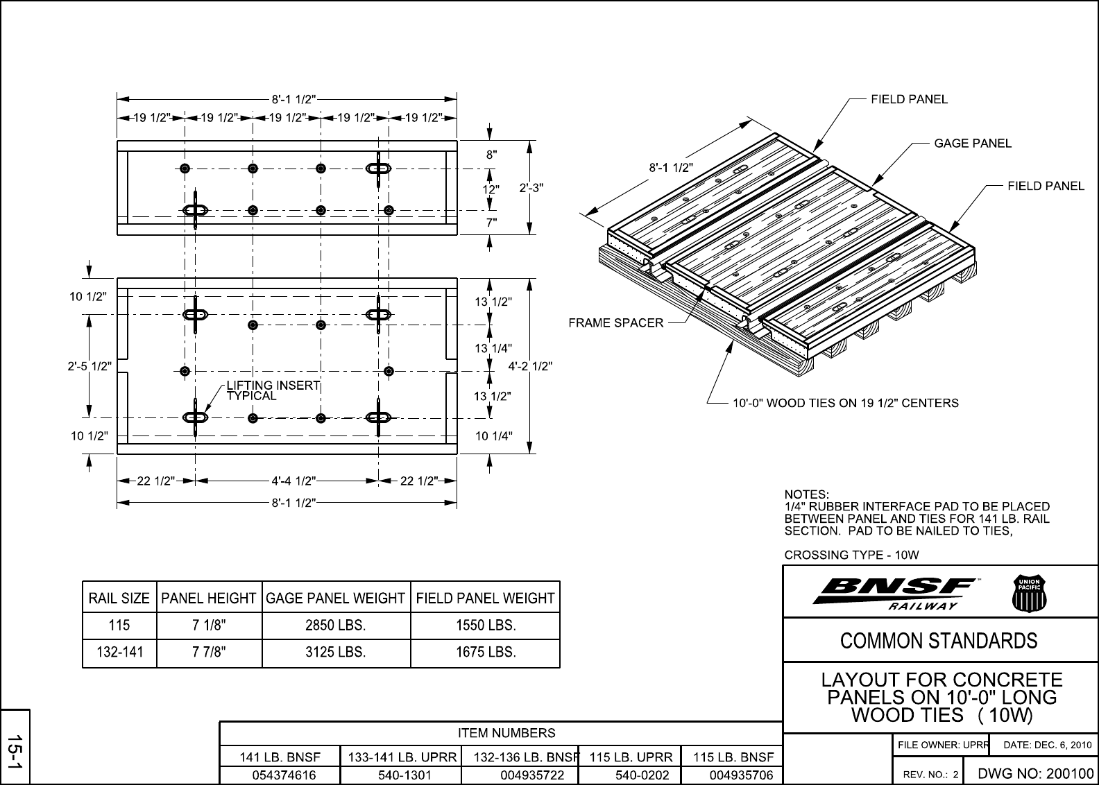
8’-1 1/2"
4’-4 1/2"
8’-1 1/2"
7"
8"
2’-3"
10 1/4"
4’-2 1/2"
10 1/2"
2’-5 1/2"
10 1/2"
TYPICAL
LIFTING INSERT
19 1/2" 19 1/2" 19 1/2" 19 1/2" 19 1/2"
12"
13 1/2"
13 1/4"
13 1/2"
22 1/2"22 1/2"
004935706
132-136 LB. BNSF
115 LB. UPRR
115 LB. BNSF
133-141 LB. UPRR
004935722
ITEM NUMBERS
132-141
115
RAIL SIZE
7 7/8"
7 1/8"
PANEL HEIGHT
3125 LBS.
2850 LBS.
GAGE PANEL WEIGHT
1675 LBS.
1550 LBS.
FIELD PANEL WEIGHT
8’-1 1/2"
10’-0" WOOD TIES ON 19 1/2" CENTERS
540-1301 540-0202
CROSSING TYPE - 10W
SECTION. PAD TO BE NAILED TO TIES,
BETWEEN PANEL AND TIES FOR 141 LB. RAIL
1/4" RUBBER INTERFACE PAD TO BE PLACED
NOTES:
COMMON STANDARDS
SM
DWG NO: 200100
REV. NO.: 2
WOOD TIES (10W)
PANELS ON 10’-0" LONG
LAYOUT FOR CONCRETE
FILE OWNER: UPRR
DATE: DEC. 6, 2010
141 LB. BNSF
054374616
15
-
1
FIELD PANEL
GAGE PANEL
FIELD PANEL
FRAME SPACER
A-42

A-43

Stock Codes Table (Login With Your BNSF email account)
Navigate to Other Drawings (Login With Your BNSF email account)
SHEET
REVISION
DATE:
STATUS
CHECKED
APPROVED
REVISED
OR
DRAFTED
PLAN NO
2509.02.04
ISC
0402
2509
BNSF RAILWAY COMPANY - SYSTEM TRACK STANDARDS
2509
.
02
.
04
20
11 15 16
2020
2 3
2 3
2 3
2 3
2 3
2 3
2 3
2 3
2 3
3
2
1
1
1
1 1
2
1
3
20 20
1
2
2
1 1 1
1
5
2 5
2
2
2
13
2
14
1
2 2
17
5
52 4
12 12 12 12 12
6
0-8
0-4 4-6
5-1
20 20 20 20 20 20 20 2020
6
6
5
6
6
7
6
7
7
6
8
8
8
8
8
12
8-0
5-0
10
21
2 3 2
5
TRACK CENTERS
VERTICAL
HORIZONTAL
M
A
I
N
T
R
A
C
K
S
G
E
N
E
R
A
L
T
H
R
U
BR
I
DG
E
S
H
I
GH
W
AY
BR
I
DG
E
S
T
UNN
EL
S
B
U
I
L
D
I
NG
DOO
R
S
I
N
B
U
I
L
D
I
NG
S
G
E
N
E
R
A
L
T
H
R
U
BR
I
DG
E
S
H
I
GH
W
AY
BR
I
DG
E
S
T
UNN
EL
S
B
U
I
L
D
I
NG
DOO
R
S
I
N
B
U
I
L
D
I
NG
S
STATE
ALABAMA
ARIZONA
ARKANSAS
CALIFORNIA
CANADA
COLORADO
IDAHO
ILLINOIS
IOWA
KANSAS
KENTUCKY
MINNESOTA
MISSISSIPPI
MISSOURI
MONTANA
NEBRASKA
NORTH DAKOTA
OKLAHOMA
OREGON
SOUTH DAKOTA
TENNESSEE
TEXAS
WASHINGTON
WISCONSIN
WYOMING
BNSF RY. CO.
CHPTR. XIII
CHPTR. TC-3
CHPTR. 480-60
SEC. 5, CHPT 11
RULE 1220-3-1-.12
ORDER F2465
ORDER 83-313
ORDER 33847
SEC.49.10.1-13
ORD 16, CHPT 5, ART 4
ADM. RULES
TTL 4 CSR 265-8.060
NR
219.47
277.240
ART. 5 -RSR
NR
TITLE 92 I.A.C.
G.O. N0. 158
DEC. 55621
CHPTR. 1189
G.O. 26-D
CASE R-1012
CHPTR. 5, ART. 1
NR
21
PLATFORMS
SIGNALS
H
E
I
GH
T
(
M
AX
)
C
LE
A
R
AN
C
E
H
E
I
GH
T
(
M
AX
)
C
LE
A
R
AN
C
E
H
I
GH
S
I
GNA
L
S
P
O
LE
S
O
R
E
AND
C
OA
L
DO
C
K
S
C
A
TTLE
C
HU
TE
S
S
U
B
S
I
D
I
A
R
Y
T
R
A
C
K
S
ANY
T
W
O
T
O
ANY
P
A
R
A
LLEL
T
R
A
C
K
L
ADD
E
R
T
R
A
C
K
AD
J
A
C
E
N
T
L
ADD
E
R
T
R
A
C
K
S
T
W
O
AD
J
A
C
E
N
T
P
A
R
A
LLEL
C
A
B
OO
S
E
T
R
A
C
K
S
YA
R
D
LE
AD
S
,
R
E
P
A
I
R
,
&
TE
A
M
T
R
A
C
K
S
I
N
P
A
I
R
S
A
T
P
L
A
T
F
O
R
M
S
UN
L
OAD
I
NG
T
R
A
C
K
S
TRACKS
BETWEEN
LOW
ETC.
BOXES,
SWITCH
T
R
A
C
K
T
O
ANY
M
A
I
N
T
R
A
C
K
S
AD
J
A
C
E
N
T
S
U
B
S
I
DA
R
Y
A
M
E
ND
M
E
N
T
Y
E
A
R
O
F
L
A
TE
S
T
H = Horizontal Clearance (Min.)
V = Vertical Clearance (Max.)
3 4 5 6 7 8 9
10 11 12 13 14 15 16 17 18 19 20 21 22 23 24 25 26 27 28 29 30 31 32 33 34 35 36 37
NR
1987
1956
1988
1983
1987
1980
1986
1982
1987
1942
1980
NR
1987
1980
1987
1981
1987
1983
1957
1970
1988
1969
1982
1979
1997
14-0
14-0
14-0
NR
14-0
NR
15-0
14-0
NR
14-0
14-0
14-0
NR
14-0
NR
14-0
NR
13-6
14-0
14-0
13-0
14-0
14-0
14-0
NR NR NR
14-0 15-0
14-014-0
14-0 15-0
14-0
13-6
15-014-0
14-0 15-0
15-013-6
NR NR
14-0 14-0
NR NR
14-0 14-0
NR NR
14-0 14-0
14-0 15-0
14-0 15-0
NR NR
14-0 14-0
14-0 15-0
NR NR
13-0 14-0
NR NR
14-0 15-0
14-0 14-0
14-0 15-0
14-0 20-0 20-0
17-0 20-0
14-0 14-0
20-0 20-0
NR NR
18-0 18-0
NR NR
20-0 20-0
17-0 20-0
NR NR
17-0 20-0
20-0 20-0
17-0 19-0
NR NR
17-0 19-0
NRNR
17-0 20-0
NRNR
17-0 19-0
20-020-0
17-0 20-0
18-015-0
20-020-0
20-017-0
20-020-0
NRNR NR NR NR
13-613-0
NR
13-014-0 22-013-0
13-013-014-0
13-6 12-0 12-0
22-6
22-613-613-014-0
14-0
22-6
23-6
22-0
13-6
13-0
21-613-6
13-0
NR
NR
NR NR NR
22-613-613-014-0
NR NR NR NR
14-0 22-014-014-0
NR
22-0
NR
14-0
NR
22-613-013-0
13-6
NR
14-0
14-0
14-0 13-0 13-6 22-6
21-0
20-9
22-013-6
NRNR
13-0
NR
14-0
NR NR
13-014-0
NR
14-0
22-0
22-6
22-6
22-0
22-6
22-0
23-0
13-0
14-0
13-0
NR
13-013-0
NR
14-0
NR
13-014-0
14-014-0
13-0
14-0
14-0 14-0
NR NR NR NR NR
18-022-023-022-0
22-022-0
22-6
22-6
22-6
22-6
22-0 22-6
22-6 22-6
21-621-3
NRNR
22-6 22-6
NR
22-0
22-0 22-0
NR NR
22-0 22-0
22-6 22-6
22-0 23-0
21-0 21-0
22-0 22-0
20-9 20-9
22-6 22-6
22-0 22-0
22-0 22-0
22-6 22-6
22-0 22-0
22-0 23-6
23-0 23-6 23-0
23-0 17-0
22-022-0
22-6 18-0
22-0
NR
22-0 17-0
17-022-6
20-9 18-0
17-023-0
21-0
23-0 17-0
18-022-6
22-0 22-0
NRNR
22-0 22-0
NRNR
23-0 17-0
NRNR
21-6
H
23-0 17-0
22-6 18-0
22-6 22-6
17-023-0
22-6 18-0
18-0
22-0
18-0
22-0
17-0
22-6
18-0
18-0
21-0
18-0
18-0
22-0
NR
22-0
NR
18-0
NR
21-6
18-0
18-0
22-6
18-0
18-0
18-0
NR NR
8-6 8-0
NR NR
8-6
NR
8-0
8-08-68-08-6
8-6 8-0 8-6 8-0
8-08-0
8-6 8-0 8-6
8-68-0
8-0 8-0
8-6
8-0 8-0
8-0
8-0 7-0
8-6
8-6
7-0
7-8
NR
7-0
NRNRNRNRNR
8-6 8-6 8-6 8-0 7-0
NRNRNRNRNR
8-6 8-6 8-6 8-6 8-6
NRNRNRNRNR
8-6 8-0 8-0 8-6 8-6
8-68-08-6
8-0
8-6
8-6 8-6 8-0 7-0
8-0
8-0
8-0 8-0 8-0 8-0
7-08-08-6
8-0
8-6
8-6
8-0
8-6 8-0 8-6
8-6
8-0
8-0 8-6 7-0
8-08-08-0
8-0
8-0
7-68-6 8-6
NR
8-6
8-68-08-68-08-6
8-6
E
8-08-6
8-6 8-6 8-6
8-08-6
8-6 8-6 8-6
7-0 7-0
8-6
8-6
8-6
8-0
8-6
8-6
7-0
8-0
8-6
8-6
8-6
NR
8-6
NR
7-0
NR
8-0
8-6
8-0
8-6
7-0
8-6
NR NR
0-8
NR
4-8
NR NR
5-94-05-00-8
0-8 4-8
NR NR
5-94-05-00-8
4-80-8 4-0 7-3
5-10-84-60-4
NR NR NR NR
6-24-05-00-8
NR
NR
NR NR
NR
NR NR
NR
NR NR
NR
NR NR
NR
NR
0-4 4-6 0-8 5-1
5-94-04-80-8
0-8 5-0 4-0 5-9
NR NR NR NR
5-94-04-80-8
0-8 4-8
NR NR
5-9
CFH
4-80-8
0-8 4-8 4-0 5-9
NRNR
4-61-0
0-8 4-8 4-0 7-3
1-9 6-0 5-0 6-4
8-64-05-94-05-00-8
8-6
8-6 3-0 6-0
6-0
E E E
0-4 3-0
E
8-6
8-6 8-0 3-0 6-0 0-4 3-04-0
4-0 8-6 8-6 2-6 5-6 0-6 4-0
3-00-46-6
NR
8-07-64-0
NR NR
8-0
NR NR
0-4 3-0
3-00-46-03-08-67-34-0
4-0 8-6 3-0 6-0 0-4 3-08-6
NR
4-0 8-0 8-0
NR NR NR
4-0 8-6 8-6 3-0 6-0 0-4 3-0
3-00-46-03-08-08-64-0
CFH
8-6 8-6 4-0 0-3 4-2
NR
NRNRNR
NR
8-6
NR NRNR
NR NR NR
NRNRNRNRNRNR
4-0 8-6 3-0 6-0 0-4 3-08-6
NRNRNRNRNRNRNR
CFH
6-2 8-6
NR NRNRNR
3-00-46-03-08-08-64-0
4-0 8-6 8-6 6-0 0-4 3-03-0
4-0
4-0
4-6
NR
4-0
NR NR NR NR NRNR
8-0 8-6 6-0 3-03-0 0-5
3-00-46-03-08-68-0
3-00-46-03-08-67-6
3-0
NR NR
8-6
8-6 8-6 8-6
8-68-6
8-6
8-6
8-68-6
NRNRNR
8-6 8-6
8-68-6 8-6
8-08-09-0
NR NRNR
8-6 8-6 8-6
NRNRNR
8-6 8-6 8-6
NRNRNR
8-6 8-6 8-6
8-68-6
8-0
8-6
8-6
8-0
8-6
12-0
8-6
8-6 8-6 8-6
8-6 8-6
8-68-6
8-6 8-6
8-68-68-6
8-0 8-0
8-68-6
8-6 8-6 8-6
8-68-6
8-0 8-0
8-68-68-6
8-6
REFERENCE
REGULATION
18
V H V H V H
1
4
1
8-4
4
1
8-4
4
1
8-4
4
1
8-4
4
1
8-4
4
1
8-4
4
1
8-4
4
1
8-4
4
1
8-4
19
NRNR
CLEARANCES BY STATES
2 4
2 4
5
GENERAL NOTES
20-0 20-0
14-0 14-0 15-0 17-023-0 18-0
8-0 7-08-08-68-6 7-0 5-94-04-80-8 0-4 3-06-03-08-68-04-0 8-6 8-68-6
17-0 20-0 13-014-0 13-0 22-6 22-0 22-6
DETAILS
HEADING
COLUMN
NO LIABILITY CAN BE ASSUMED
THIS CHART IS FOR INFORMATION ONLY
check with state(s) involved
Architects, contractors, etc. should
Applies to both supports and platforms except as noted
37
Passenger platforms
24 & 25
To center of stand except as noted
36
Bridges spanning tracks
14 & 20
Other than trolley contact poles
35
Bridges supporting tracks
13 & 19
Stepped platforms not allowed
Prevails for all items not otherwise provided for
12 & 18
Freight Platforms on side tracks
28 & 29
Apply to hand and mechanically operated switches except as noted
7 & 8
Passenger / freight platforms on side tracks except as noted
26 & 27
Shows basic regulation, effective year or year of latest amendment
& 3
2
NEW MEXICO
NMAC 18.14.2.9(B)
2011
May be 8-0 at 4-6 for refrigerator car platforms only
8
Passenger platforms only
7
Only if 8-0 (7-3 for MT & WY; 8-6 for WA & SD) provided on opp. side
6
May be reduced to 5-9 if 8-0 (8-6 for NE, MO & WY) provided on opp. side
5
May be reduced to 5-9 if 8-3 (8-6 for WY) providied on opposite (opp.) side
4
Only if tracks end within buildings
3
lesser dimensions
builds exempt / permitted
Engine houses and shop
2
permitted in quadrants
Lesser clearances not
1
FOOTNOTES
21-0
LEGEND
BNSF 2509.01 BNSF 2509.03
&
3/18/2019
BNSF STANDARD PLAN
TRACK STANDARDS
CLEARANCE REQUIREMENTS BY STATE
AND RECOMMENDED BNSF CLEARANCE
1
C/L
rail
of
Top
H
H
H
1
V
1
V
V
322
3
2
2
3
3
May be reduced to 6-2 if 8-0 provided on opposite side
14
May be reduced to 6-2 if 8-3 provided on opposite side
13
by board of transport commissioners for Canada for railway involved
Regarding Canada - Check standard clearance diagram approved
12
For freight tracks - can be 13 for passenger tracks
11
For platforms at car eave height - supports to be 8-0 (8-6 for TX)
10
For a visual illustration of these use cases and additional information on main line related clearances, see
6.
Dimensions are based on maximum car size for California, Idaho, Minnesota, Montana, North Dakota, Oregon, and Washington states.
5.
Application cases vary, from only to new construction, some reconstruction, and to some extensions. They can be changed upon approval by applying to governing body.
4.
Vertical clearances are measured from top of rail, except Canada using the base of rail for other than platforms. Horizontal clearances are measured from the center line of track.
3.
All are minimums except columns 24, 26, 28, 31, and 33 which are maximums.
2.
Dimensions are shown in feet and inches for tangent track. Most laws specify increases for curved and superelevated track.
1.
NR = No current regulations known
E = Exempt
H = Height of car governs
CFH = Car floor height
Released
EKF
EKF
Center line of track to closest edge of pier: 25' for main line, 18' for others
21
State regulation governs
20
New construction 20-0 center to center main track / control siding
19
Must have additional side clearance of 2 inches per degree of curvature
17
For hand operated switches (May be 17-0 for mechanically operated switches)
16
For hand operated switches (May be 15-0 for mechanically operated switches)
15
A-44

Stock Codes Table (Login With Your BNSF email account)
Navigate to Other Drawings (Login With Your BNSF email account)
SHEET
REVISION
DATE:
STATUS
CHECKED
APPROVED
REVISED
OR
DRAFTED
PLAN NO
2509.01.11
EKF
ISC
1101
2509
BNSF RAILWAY COMPANY - SYSTEM TRACK STANDARDS
2509
.
01
.
11
FOR CLEARANCES
DIAGRAM
ILLUSTRATIVE
GENERAL NOTES
BNSF 1001.00 / CS 100100
BNSF 2509.01
BNSF 2509.03
BNSF 2509.02
BNSF 2509.02
BNSF 2509.02
&
(Field Side)
Switch Stands
Signals or
for signals & interlockers
other switch mechanisms
Switch machines or
Caboose tracks
Repair tracks
Industry tracks
House tracks
Team tracks
All poles, posts, and similar features
(4 & 6)
20'-0" Mainline tracks
(6)
20'-0"
20'-0"
(7)
(33 & 34)
(30 & 34)
20'-0"
(7)
14
'
-
0
"
14
'
-
0
"
(
5
)
(
5
)
8'-6"
(35)
(35)
8'-6"
14'-0"
14'-0"
(9 & 10)
(9 & 10)
(11)
State regulations govern
BNSF 1001.00 / CS 100100
(24 - 29)
Low platform
High or
Warehouse unloading platforms
(31)
6'-0"
(32)
6'-0"
(32)
T
w
o
o
r
m
o
r
e
p
a
r
a
ll
e
l
t
r
ac
k
s
20
'
-
0
"
(
8
)
ALL STRUCTURES (BNSF)
CLEARANCE ENVELOPE
(12 - 23, 36 & 37)
may be more restrictive
8'-6" Min. - Signal Instructions
(24 & 25)
(26 & 27)
(28 & 29)
Top of rail
8' 6"
refer to
Stepped platforms are not allowed. For additional information regarding platforms,
5.
For new construction track centers, refer to
4.
For existing track centers, refer to
3.
Numbers in parenthesis represent column numbers for dimensions in columns per
2.
for details. State or federal regulations supersede BNSF recommended clearances.
Dimensions shown are BNSF general clearances only. Where dimensions are not shown, refer to
1.
8
'
6
"
R
Centerline of track
between tracks
Switch Stands
Signals or
Ladder Tracks Ladder Tracks
Platform clearances
23
'
BNSF STANDARD PLAN
TRACK STANDARDS
BNSF MINIMUM CLEARANCE
DIAGRAMS & ILLUSTRATIONS
3/18/2019
Released
EKF
A-45

A-46

VERTICAL CURVES
Revd 12/11/2012
Vertical curves should be used to round off all intersecting grades.
The length of a vertical curve is determined by the grades to be connected and the
speed of the traffic.
The rate of change for tracks with a vertical curve concave upwards (sag) should be
one-half the rate of change of a vertical curve concave downward (summit).
The rate of change for high-speed main tracks (> 50 MPH) should not be more
than 0.05 feet per station (of 100 feet) in sags, and not more than 0.10
feet per station on summits.
For secondary main tracks (speed < 50 MPH), the rate of change should not be
more than 0.10 feet per station in sags, and not more than 0.20 feet per
station on summits.
For industry tracks and non-main tracks with speeds not greater than 20 MPH,
the rate of change should not be more than 2.0 feet per station for both
sags and summits.
The rate of change per station is calculated as follows: R = D/L Where:
R = Rate of change per station
D = Algebraic difference of the two intercepting grades
L = Length of vertical curve in 100-ft. stations
M = Correction from the straight grade to the vertical curve
A parabola is used for the vertical curve in which the correction from the straight grade
for the first station is one half the rate of change, and the others vary as the square of
the distance from the point of tangency. Where points fall on full stations, it will be
necessary to figure these for only one half the vertical curve, as they are the same for
corresponding points each side of the vertex. Corrections are (-) when the vertical
curve is concave downwards (summit), and (+) when the vertical curve is concave
upwards (sag). The rate of change may be assumed and the length of vertical curve
computed, or preferable the length assumed and the rate computed.
A-47

VERTICAL CURVES
Revd 12/11/2012
For example:
Assume length = 600 feet (6 stations)
D – 0.50 minus –0.22 = 0.72
R = 0.72/6 = 0.12
Calculate the straight-grade elevations for each station.
The correction for the first station is one-half the rate of change (R). So, the correction
for station 11 is 0.06 (minus since it concaves downwards).
The correction for the Station 12 is 4(0.06) = 0.24. This is the correction to the first
station (one-half the rate of change) multiplied by the square of the length, in
stations, from the PVC. At Station 13 (the PVI), the correction is 9(0.06) = 0.54.
Notice the corrections for Stations 11 and 15 are the same. Likewise, for 12 and
14, since they are the same distance from the PVC and PVT. So, only one-half of
the curve’s corrections need to be calculated.
Next, apply the correction at each station to the straight-grade elevation to obtain the
elevation on the vertical curve.
A simpler method of computing this and one that furnishes check throughout is the
following:
Sta. 10 90.00
+0.44 (% grade sta. 9 to 10) minus one half rate = 0.50 – 0.06
Sta. 11 90.44
+0.32 (% grade sta. 10 to 11) minus rate = 0.44 – 0.12
Sta. 12 90.76
+0.20 (% grade sta. 11 to 12) minus rate = 0.32 – 0.12
Sta. 13 90.96
+0.08 (% grade sta. 12 to 13) minus rate = 0.20 – 0.12
Sta. 14 91.04
-0.04 (% grade sta. 13 to 14) minus rate = 0.08 – 0.12
Sta. 15 91.00
-0.16 (% grade sta. 14 to 15) minus rate = -0.04 – 0.12
Sta. 16 90.84
A-48
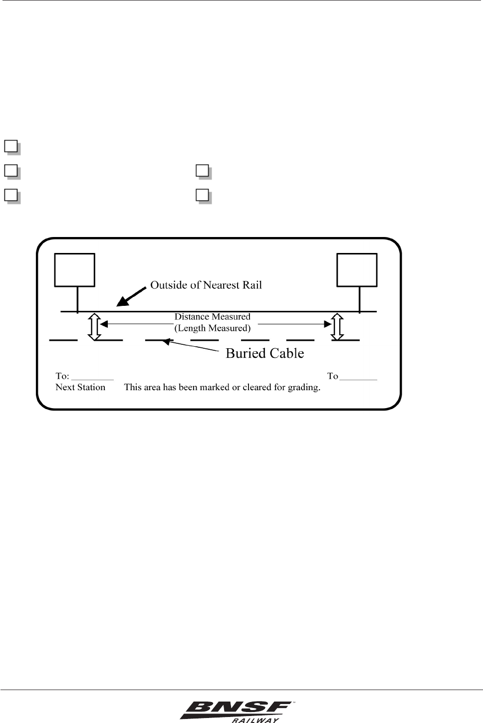
26 Underground Utilities
Engineering Instructions
Revision: January 1, 2012
26-9
BNSF Railway
Underground Cable Location and Acknowledgement
Date: ________________ Project: _________________
Meeting Location: ______________________ Time: ___________________
Attendees at proposed work site (Signature of representative)
BNSF Telecom ____________________
BNSF Signal ______________________ Grading Contractor __________________
Project Inspector ___________________ Flag Person on Duty _________________
No grading will be permitted in this area without this completed form in the possession of the above.
Notes:
All signal cables must be marked with paint and ags (as ground conditions permit) prior to any grading.
____________________________________________________________________________________
____________________________________________________________________________________
____________________________________________________________________________________
____________________________________________________________________________________
____________________________________________________________________________________
____________________________________________________________________________________
Copyright BNSF 1999 Revision: October 15, 2004
Figure 26-1. Underground Cable Location and Acknowledgement
A-49

A-50

I acknowledge that I have received the internet link and/or hard copy of BNSF’s
“Guidelines for Industry Track Projects” dated July 2023. I understand that the
design and construction of this facility will follow the Guidelines. Questions concerning
the Guidelines are to be directed to the BNSF Project Engineer listed below.
https://www.bnsf.com/ship-with-bnsf/rail-development/pdf/IndustryTrackGuidelines.pdf
(Industrial Track Guidelines)
https://www.bnsf.com/bnsf-resources/pdf/about-bnsf/utility.pdf << Utility Specs
Owner Representative
_______________________________________________ __________________
Signature Date
__________________________________ ______________________________
Printed Company Name
__________________________________
BNSF Project Engineer
A-51
