
Electric Fencing 0
Electric Fencing Systems Design, Installation
& Maintenance

2
Electric Fencing 101
Contents
Disclaimer: While every effort has been made to ensure accuracy,
neither Gallagher Group Limited or any employee of the company will be
liable on any ground whatsoever to any party in respect of decisions or
actions they may make as a result of using this information.
In accordance with the Gallagher policy of continuing development,
design and specifications are subject to change without notice.
Why Use Electric Fencing?
Getting Started
Powering Your Fence
Fence Construction
Permanent Fencing
Offset Fencing
Temporary & Portable Fencing
Fault Finding
Safety
Troubleshooting
04
08
09
19
20
32
34
42
44
50

5
4
NZL Cattle
3. Animal receives shock when it touches the fence.
1. Energizer (power) is connected to the fence and the ground.
2. Power is sent along the fence in pulses.
Why Use Electric Fencing?
A short, safe and memorable shock to create a psychological as
well as a physical barrier.
Why Use Electric Fencing?
How Electric Fencing Works
• Keeping domestic animals in
• Keeping wild animals out
• Separating different groups of animals
• Rationing of crops and pastures
• Fencing off eroding areas, trees, rivers and roads
At a basic level electric fencing is more effective at containing domestic
animals livestock/excluding wildlife than traditional fencing due to the fact
that the short, safe and memorable shock creates a psychological as well as a
physical barrier.
A pulsed electric current is sent along the fence wire, about one pulse per
second, from an energizer which is grounded. When the animal touches the
fence it completes the circuit between the fence and the ground receiving a
short, sharp - but safe shock. The shock is memorable enough that the animal
never forgets.
An electric fence is a psychological barrier, so it doesn’t need great physical
strength. However, it must be well designed and constructed to absorb some
pressure from animals, snow and wind. The energizer must have enough power
for the length of fence and for the animals being controlled.
Electric fencing is a reliable, cost effective way to control animal movement
and manage pasture. This includes:

7
6
KEY BENEFITS
Effective
Maximize results potential of feed and
greatly improve the feed quality and
yield.
Efficient
Direct harvesting of grass or fodder
crops by the animal with manure
returned directly to the soil during the
process.
Flexible
Use a combination of permanent &
portable fencing to maximize grazing
area control.
Beyond just keeping animals in and
out, electric fencing is the best way
to achieve optimum pasture yield
using rotational grazing methods.
This approach works by keeping
the grass fresh, short and palatable
which ultimately leads to increased
meat and milk production as well
as reduced supplemental feed
costs. It involves grazing paddocks
in rotation using a combination of
permanent and/or temporary fenced
grazing areas.
Pasture Management and Rotational Grazing
KEY CONSIDERATIONS
Achieving optimum pasture growth is
a delicate balance. When considering
how best to meter out the pasture feed
available look at the following:
1. Number & size of grazing areas -
grazing specific areas, so other pasture
sections are able to rest and re-grow.
2. How many animals to put on that
grazing area - efficiently grazing the
allocated area.
3. And for how long – graze to desired
residual grass height
The combination of these factors
determines the rotation length (how many
days before the first area in the rotation
is grazed again). The optimum rotation
length varies significantly depending on
the geographical location and time of
year.
The more regular the shift (preferably
daily or every few days) the more time the
pasture spends growing rather than being
grazed, leading to greater grass growth
and stock carrying capacity.
Where a permanently fenced paddock is
further subdivided using portable electric
fences the stock are contained by both
a front and a back fence. The back fence
protects the recently-grazed area to allow
it to recover so it can be grazed again
sooner.
Subdivision with high stocking density
ensures grass is harvested down evenly
to the optimum residual length, and that
over time manure is spread more evenly
over the whole grazing area.
Why It Works
Maintaining grass at the high growth
tilling stage ensures young, lush,
green pasture with high protein and
energy levels. Grazed and rested for
the right amount of time creates the
ideal conditions for grass growth
when the plants produce leafy shoots
from the base.
There are various grass varieties to suit
different environments. Longer term
options last 10 years or more and shorter
term annuals can give extra yield over a
shorter time-frame.
Forage crops (i.e. turnips, kale, sorghum
etc.) are low cost to establish and can be
used to fill feed deficits during cold and/
or dry months where grass growth slows
or stops altogether. Direct grazing of
such crops using portable electric fencing
eliminates harvesting and feeding out,
with animal waste being returned directly
to the land.
If you farm sheep intensively, you may
want as many as 100 paddocks. This
means the sheep can be moved daily
onto a fresh paddock using a three month
rotation during slow or zero growth
periods. When there are lambs and ewes
during spring, two or more flocks can be
grazed on a faster rotation.
For beef and dairy producers 30–50
paddocks are usually enough. Cattle are
easy to strip graze with only one wire when
longer rotations are necessary during slow
growth periods.
Managed Grazing Examples
Why Use Electric Fencing? Why Use Electric Fencing?

9
8
Getting Started
Every electric fence system is made up of a:
• Power System
• Fencing System
Selection of these depends on property size, fencing usage and animal type.
Power System
Fence System
1. What do you want to achieve with
your fencing?
• Determines permanent and/or
temporary subdivision
2. How long do you want it to last?
• Some products are designed to
last well over 10 years others while
others are warranted under 10
years
3. What animals are you trying to
keep in/out?
• Influences the fence setup like the
number of wires & spacing
• Impacts product choice. For
example, horses have special
requirements
1. Do you have a reliable power
source?
• Will determine Energizer type –
110v or battery (including solar
options)
2 How much fencing are you looking
to power?
• Distance influences Energizer size –
and fence construction
3. What is your location?
• Grounding is critical to good power
transfer, drier areas need different
fencing set-ups and more grounding
to compensate
• Solar energizer options are perfect
for remote locations with good
sunshine
Energizers
All Gallagher Energizers are low-
impedance and guarantee a high-energy
pulse. Selection is based on power
availability, fence length, number of wires,
vegetation touching the fence, application
(does it need to be regularly moved) and
the number of animals (fence pressure).
The only true way to compare different
Energizers is based on STORED JOULES,
it is a constant measure and not affected
by variations in fence conditions or
grounding.
Stored Joules – How it works
Like horsepower on a vehicle. It is the
potential power in the engine to maintain
speed no matter what the vehicle is pulling
behind, or what the gradient of the road is.
In an Energizer, power from either a 110V
outlet or battery source enters the unit
and is stored in capacitors. This stored
energy is the potential power available
in the single pulse per second generated
when the animal touches the fence. The
higher the stored joule rating the greater
the Energizer’s ability to push past shorts
caused by weeds and fence faults and
maintain fence voltage, as well as cover
future fence expansion.
Gallagher Recommends Always
purchase the highest powered
Energizer you can afford. More
power provides more confidence
that the fence will perform despite
unexpected shorts like vegetation
growth. Also electric fence systems
tend to grow, so purchase an
Energizer with headroom to power
additional future fence.
Powering Your Fence
Energizer Selection
TERMS
Voltage - a measure of electrical
‘pressure’ that drives current flow
Current (amps) - a measure of the
flow of electrical energy
Stored Joules - the amount of
energy stored in the energizer
available for each pulse
Output Joules - the energy
discharged on the fence for each
pulse
Pulse Shape - the shape of the wave
of energy traveling down the fence
line
Gallagher’s range of Energizers
continues a proud tradition of the
world’s best engineered products
1) Indicator lights on all Energizers
tell you at a glance that the
Energizer is operating
2) All energizers are fitted with
lightning protection and are fully
modular for rapid servicing and
replacement
3) Gallagher’s reputation for
worldwide service and satisfaction
has endured for over 80 years
4) All Energizers purchased after
January 1, 2018 carry a three year
warranty.

11
10
Powering Your Fence
Energizer Selection
Types of Energizers
110V, Plug-in Energizers are the best
choice if you have access to a power outlet.
The Energizers are reliable in every situation
with exception of a power outage and will
provide you with the most power for the least
about of money. You will need to install them
inside a structure where they are protected
from moisture.
Battery Energizers are typically portable
and great for remote areas far from power
outlets especially in cases where they are
periodically moved. These are powered by a
12v rechargeable battery, “D” cell batteries
or a 9 volt disposable dry cell battery.
Solar Energizers are portable and an
excellent choice for temporary fence
applications. They are a logical choice
for remote areas where there is no 110V
outlets. While they have the highest upfront
cost per joule, the power to operate them is
free as long as they have adequate sunlight.
The solar panel charges the battery by
converting light directly into electricity. The
battery stores this electricity to operate
the energizer. This enables the energizer
to operate at night or during periods of low
sunlight.
Multi Powered Energizers combined with
various adaptors will allow you to power
your Energizer using any one of the methods
listed above: 110V Outlet, Battery or Solar.
This is a great choice if you move your fence
to locations where 110v power will exist and
other locations where it is not available.
Powering Your Fence
Energizer Selection
Gallagher Recommends – comparing on stored joules only, since these distance/acreage ratings are
always manufacturers estimates because two properties of the same acreage/fence distance may
have dramatically different conditions e.g.: number of wires, vegetation growth, stocking intensity.
STORED
JOULES
‘UP TO’
DISTANCE
CLEAN FENCE
(MILES/ACRES)
RECOMMENDED
DISTANCE
TYPICAL FENCE
(MILES/ACRES)
I SERIES
OPTION
LIVESTOCK CONTROLLED
M10000i 100.0 1,000 / 6,000 125 / 3,000
•
M5800i 58.0 430 / 2,700 87 / 2,200
•
M1500 15.0 160 / 900 40 / 360
M1100 11.0 110 / 650 36 / 280
M800 8.0 90 / 520 30 / 200
M560 5.6 75 / 400 23 / 130
M360 3.6 55 /250 19 / 95
M160 1.6 30 / 100 11 / 60
M120 1.2 15 / 60 6 / 30
M60 0.6 10 / 40 3 / 20
M30 0.3 5 / 20 2 / 10
M10 0.1 2 / 10 0.5 / 3
MBS2800i 28.0 250 / 1,500 50 / 1,000
•
MBS1800i 18.0 200 / 1,200 42 / 420
•
MB1000 10.0 100 / 600 34 / 250
MBS800 8.0 90 / 520 30 / 200
MBS400 4.0 60 / 280 20 / 120
MBS200 2.0 45 / 160 14/90
MB150 1.5 30 / 100 11 / 60
B60 0.6 15 / 60 5 / 40
B11 0.11 4 / 20 0.6 / 6
B10 0.1 4 / 20 0.6 / 6
S400 4.0 60 / 280 20 / 120
S200 2.0 45 / 160 14 / 90
S100 1.0 30 / 100 8 / 60
S40 0.4 25 / 80 5 / 30
S20 0.20 12 / 40 2 / 14
S16 0.16 10 / 30 1 / 10
S10 0.1 3 / 15 0.5 / 5
ALL IN ONE SOLAR
MULTI-POWER
110 VOLT
BATTERY

13
12
i
Powering Your Fence
i Series Fence System
Powering Your Fence
i Series Fence System
ALARM SYSTEM
Secure your
assets
The i Series Energizers have extremely reliable power that adapts output up or down
depending on your fence conditions. Each one also comes with a separate controller that
can be mounted outdoors for easy fence performance checks.
3
2
2
4
1
5
2
5
Once the fault is repaired, power is
restored to the fence and tested using
the Remote.
ON
OFF
Power to the fence at the fault location
is turned off using the Remote, allowing
a safe and convenient repair.
4
Fence Monitor(s) recognize any
significant drop in fence zone or
Energizer performance and raise alarms.
1
Alerts are sent to the Energizer
Controller and/or optional Alarm System.
2
3
The Controller and Remote indicate
which zone is in fault. The Remote is
used to find the fault within the zone.
Quickly locate
and repair faults
ENERGIZER REMOTE & FAULT FINDER
i Series Fence Energizer Systems
Create fence
zones and
monitor fence
performance
around your
property
FENCE MONITOR
ENERGIZER CONTROLLER
Easily monitor
and control fence
performance
ENERGIZER
Reliable and
adaptive
performance
even in extreme
conditions
How the System Works:
On i Series models you can also add
monitors around the fence line that
feed information back to the
Controller and tell you if all is well or
if there is a fault in their area.
The Remote & Fault Finder helps
pinpoint any faults quickly, saving
hours hunting for and fixing the
issue.

15
14
Energizer Size Required Ground Rods
Up to 15 Joules 3 Rods minimum
Up to 28 Joules 6 Rods minimum
Up to 58 Joules 12 Rods minimum
Handy Hint
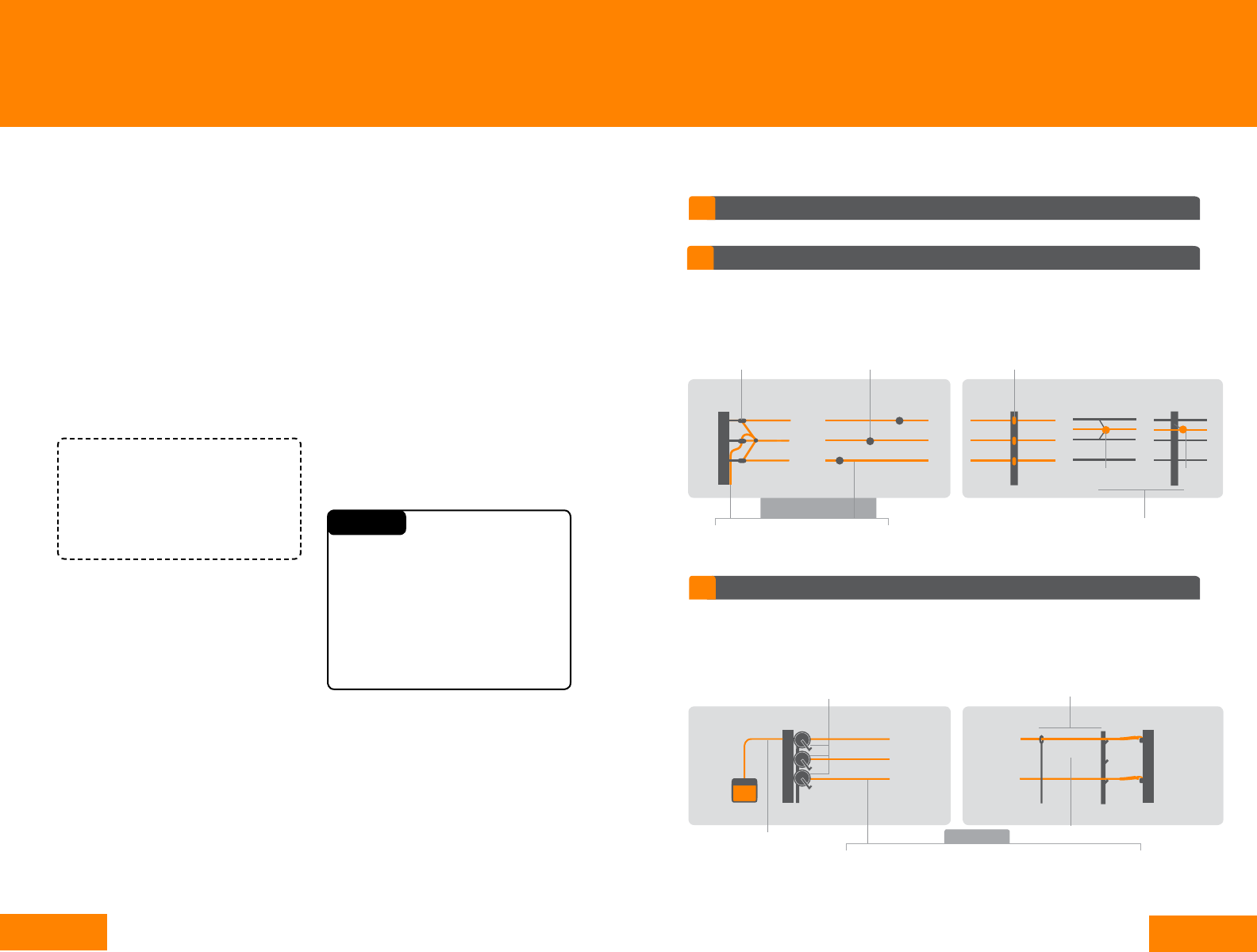
Grounding Systems
The ground must be as conductive as possible for the fence to give the animal an
effective shock. A simple guide is one ground rod for every five joules of stored
energy with a minimum of three ground rods.
Additionally you will need to setup your electric fence according to how ‘green’ the
area is all year round.
All Live Wire System
– best suited for wetter regions
For use in greener regions with
good ground conductivity. All
fence wires connect to the red
terminal on the Energizer and a
shock is delivered to an animal
when it’s touching the ground
and the fence at the same time.
Ground Return Wire System
– best suited for drier regions
For use where the ground
struggles to conduct enough
power (for year-round dry, frozen
or snow conditions). The live &
ground wires on the fence
create the shock when the
animal touches them both at the
same time.
Don’t Do
Allow bare wires to touch an iron clad
building - use double insulated cable
Keep energizer ground system 33-40’ away
from other electrical ground connections
Do not use rebar for ground rods
Keep energizer ground system 33-40’ away
from any metal pipes carrying water
Do not use copper lead-out wire
or copper ground rods.
Use galvanized ground rods. Rusty or
corroded ground rods will not be effective
Place near fertilizer, animal urine and
manure (corrosion)
Locate rods where soil tends to stay moist,
north sides of buildings, low spots
Place your ground rods where they are
likely to be hit by equipment
Use high conductive cable for connecting the
Energizer to the ground system and fence
When constructing ground return wire fences,
re-ground negative wires with a ground rod
every 1,200’
i
Powering Your Fence
Grounding
Powering Your Fence
Grounding
The rule for ground rods when installing permanent fencing
10’ Between ground rods
3 Ground rods minimum
Grounding
Live Fence
6’ Minimum length of rods
1 Wire connecting all rods to Energizer ground terminal
As a rule of thumb, use at least 3 ground rods or the Energizer Stored Joules rating
divided by 5.
Grounding
Live Fence
Follow the recommendation in the chart
to get the maximum benefit. When in
doubt, add more ground rods. The number
of ground rods will vary depending on
the power of the energizer and the soil
type. High powered energizers need more
ground rods than low powered energizers.
Dry, sandy, rocky or frozen soil will require
more ground rods than wet soils.
Why does the Energizer need a ground
system?
The ground is half the circuit of your
fencing system. Electrons travel from
the energizer, along the fence wires
and back through the ground to the
Energizer to complete the circuit. Like a
radio antenna collects sound waves, the
ground system collects the electrons.
The ground must be as conductive as
possible for the fence to give the animal
an effective shock.
Main causes of a poor ground
system are:
• Rusty or corroded ground rods
• Broken ground wire connecting
the rods
• Not enough ground rods
• Ground rods too close together
or too short
• Poor connections at the rod or in
the connecting wire

17
16
i
Powering Your Fence
Basic Fault Finding
Powering Your Fence
Testing Your Power
This should be done once a short section
of fence has been built. You should test
your system at least once a year at the
height of any dry period to ensure the
grounding capacity is sufficient for the
joule rating of the energizer.
Short the fence out at least 330’ away
from the ground system by using several
ground rods between the wires and the
ground. Reduce the fence voltage at this
point to 2000V (2kV) or less.
Using a Volt Meter, measure the voltage
between the wire connecting through
the ground rods to the Energizer ground
terminal and an independent ground rod.
This rod should be a galvanized metal
rod, minimum 8” long. Place the rod 3’
away from the ground rods or as far away
as your Volt Meter cable will reach.
There should be no reading on the Volt
Meter; however, up to 200V (0.2kV) is
acceptable. If the voltage is higher than
this, switch off the Energizer, drive in
more ground rods at the recommended
spacings and connect them to the
existing ground system until the voltage
is down to the acceptable level.
Testing on All Live Wire Ground System
Install a 6’ ground rod as close a possible
to the end of the fence. Install a 500
ohm load tester between a hot wire and
ground wire. Choose the location for the
ground rod in a damp area if possible. If
you cannot find a damp area, the ground
test may be unreliable.
Using a Volt Meter, measure the voltage
between the hot wire and the ground wire
across the load tester you just installed.
Next measure the voltage between the
hot wire and the independent ground rod,
leaving the load tester in place.
If the second voltage reading exceeds
the first by more than 1000V (1kV)
check the ground return wire for loose
connections.
Finally, connect the independent ground
rod to the ground return wire as a
permanent connection.
Extra ground rods can be added at
various places around the fencing system
and connected to the ground return wire
to improve ground performance.
If the first voltage reading is less than
3kV, your fence system is at risk of poor
animal control.
Assuming that your ground wire return
checked out satisfactorily, check that the
fence hot wire has good connections. If
connections are good, it is possible that
your energizer is too small for your fence
system. Assess your total length of fence
or property size against the energizer
selection chart on page 11.
Testing a Ground Return Wire System
The current flow on the fence will vary
depending on the size of your Energizer,
amount of vegetation and the size of
your fence system. With time you will
learn the normal current flow on your
fence.
Fence tools and testers are another
useful accessory to have on hand when
building, maintaining or checking an
electric fence. Gallagher has two fence
testers, both available from your local
Gallagher Dealer. The Fault Finder is a
all-in one device, current meter and fault
finder. The Volt Meter measures volts
only.
To obtain the best results from your Fault
Finder, Gallagher recommends that you
check the current while the fence is
opererating without any faults. Then,
when you suspect there is a fault on the
fence line, you can compare the current
flow with the “normal” current flow.
This will indicate whether a fault exists
and, if so, how much the fault is affecting
the performance of the fence.
1. The Arrow on the LCD will indicate
which direction the current is flowing.
2. Following the direction of the current,
take readings approx. every 330’ or at
junction points along your fence line.
Note: At a junction point, follow the wire
with the highest current flow.
3. A fault is indicated by a drop in current
flow between two checkpoints. The fault
will be somewhere between the two
checkpoints.
4. To narrow down location of the fault,
work back along the fence checking the
current flow at shorter intervals.
5. Correct the fault.
6. After correcting the fault you should
see the current reading drop and the
voltage group. If not, check for
further faults.
See page 50 for more troubleshooting help
using a Fault Finder.
Multi-wire fences connected in parallel will have similar current flowing in each
wire. To get the total fence current flow, add together the current flow in each
wire.
HANDY HINT:
Using a Fault Finder
Fence Volt Meter
G503014
Fence Volt/Current
Meter and Fault Finder
G50905
19
18
i
Powering Your Fence
Lightning Protection & Leadouts
End strain assembly
provides an insulated
attachment between
the wire and the strainer
posts at each end of the
fence.
Hi-Tensile
Wire
Double
insulated cable
In line straining
allows the fence to
be tensioned and
re-tensioned as
required.
Insulators attach the fence wire to the
posts, keeping the wires at the correct
spacing and height.
Offsets specific to Offset Fencing, hold the
electric wire off the existing non-electric fence
wire or posts on a conventional fence line.
Post
Mount
Wire Mount
Fence Wire Types
Braid/Tape
Permanent electric fences for highly effective animal control that lasts a lifetime.
2
Offset Fencing
Extend the life of an existing conventional non-electric fence by retrofitting an electric wire.
Easy to transport, assemble and take down for short-term animal control or rotational grazing.
Reels hold the tape, braid or wire for the portable
fence. You can use just one reel for single line
fences or up to three reels, attached to a reel
stand, for multi-wire fences.
Tapes, Wires and Braids are used on portable fences rather than the
high tensile galvanized wire used on permanent fences. Gallagher
conductors are ideal for portable electric fences as they are light,
visible, easy to wind and durable.
Power Connectors
are leads that connect
a portable fence to an
existing permanent
electric fence.
Portable Posts are lightweight yet sturdy.
Pigtail and Ring Top posts are most popular for
cattle fences and multi-wire treadins are used
for all livestock fences.
Permanent Electric Fencing
1
3
Temporary/Portable Fencing
Fence Wire
Selection of the right fencing systems depends on property size, fencing usage and
animal type. Use this electric fence guide to help you configure your fence based on your
usage and the animal(s) you will be fencing.
Fence Construction
Lightning Diverters
Lightning will likely damage your
Energizer if it strikes your electric fence.
Gallagher Energizers have internal
lightning diverters that give partial
protection against small strikes.
Since lightning always finds the easiest
way to ground, installing a Lightning
Diverter will give added protection by
providing a path for any lightning that
strikes the fence to be diverted to the
ground.
Otherwise disconnect the Energizer
from the fence and power supply during
lightning storms.
Leadout
Leadout describes the cable and wire
that carries the power from the Energizer
to the middle of your fence system. It can
be either run overhead or underground.
Insulated leadout cable should be used
to prevent the leadout from shorting out
on obstructions or the ground and should
be used in buildings, under gateways
and where soil could corrode exposed
galvanized wire.
Undergate cables should not be used for
long leadouts or for long distances
underground, because 16 gauge
galvanized wire will cause resistance to
the flow of current reducing the available
voltage in the fence.
This is not so important on small
properties, but where medium sized
distances of fencing are to be erected
(<10 miles), use 12.5 gauge leadout
cable. On large properties powering large
energizers larger than 20 joules, high
conductive cable should be used.
Never use household electrical cable; it is
made for a maximum of 440 volts and for
inside work only.
Never use copper wire cable because
electrolysis problems occur where it is
joined to galvanized fencing wire.
Keep resistance to a minimum and ensure
maximum power transfer around your
property by choosing the cable with the
lowest ohm’s rating.
Using the diverter does not guarantee
complete protection. In bad lightning
areas, grounding the top fence wire
helps significantly by encouraging
the lightning to get to ground without
passing through the Energizer.
NEVER use household electrical
cable. It is made for low voltage use
only.
NEVER use copper wire/cable
because electrolysis (electrical
corrosion) occurs where it joins
galvanized wire.
CAUTION

21
20
Animals quickly learn to respect
electric fences and keep away
– so the fence looks good for
longer, and your investment is
protected.
Gallagher’s Insulated
Line Post makes fence
construction easy giving a low
maintenance and attractive
fence.
High quality, long lasting
electric fences cost less
than other traditional fencing
options.
High tensile wire systems
create long life, permanent
electric fences. They are
easy to install and provide
highly effective animal
control that lasts.
Permanent fences
use highly conductive,
corrosion resistant fence
wire together with wood,
t-posts, fiberglass and
Gallagher insulated
line posts, couple with
components to keep fences
looking good and working
effectively for a life time.
Cattle
Pigs, Sheep, Goats
Fence Set Ups
23-33’
14”
14”
14”
10”
6”
6”
6”
23-33’
10”
Permanent Fencing
1.
Horses are lively and
at times unpredictable,
so keeping them safely
contained is paramount.
A Gallagher equine fence is
a safe, reliable and highly
visible solution designed to
ensure your horses’ welfare.
Three options are commonly
used for long term equine
electric fencing – a
permanent fence using the
new Equine Fence Wire,
semi-permanent Tape or
Braid fences.
A semi-permanent Tape fence
is highly visible, simple to
construct and will last years,
making this type of fence an
economical and popular choice
for horse owners.
Turbo Braid can be used as a low
tension semi-permanent fence
alternative to Equine Fence Wire.
Braid is designed not to tangle or
overstretch and is easy to install.
Equine Fence Wire is the safest,
most effective electric fence for
your horse. This long life, high
tension fence uses specially
designed wire coating to reduce
risk of injury.
12”
12”
24”
23-33’
Horses

23
22
Permanent Fence Building
Fence Posts
Permanent Fence Building
Fence Tools
While the heart of your electric fence is
your energizer, fence posts are the
backbone of your fence system.
A permanent fence post needs to stand
straight and solid for many years.
Permanent fence line posts typically have
about one third of their length
underground, so add half as much again
to the height of your fence to determine
the post length. End and corner posts
typically have as much in the ground as
above.
There are three basic types of permanent
fence posts: wood, steel, fiberglass.
Wood Posts
Round wood posts provide the basis for a
strong permanent power fence. Gallagher
offers a range of insulators for
attaching electric fence wires to wood
posts, including special equine fencing
products for Equine Fence Wire, braid
and tape. Insulators can be attached
to the post using staples, screws or flat
head nails.
Posts can be installed by digging a hole
and then manually backfilling and
tamping the post tight, or by driving the
post into the ground using a tractor or
trailer mounted post driving machine.
Post spacing depends on the number of
wires, wire type and terrain and can vary
between 15-30’. Post spacing can be
extended if fiberglass, wooden or
insulated wire droppers are installed
between the posts.
Steel Posts
A steel t-post offers a simple line post
alternative to a wood post. Steel posts
have the advantage of being able to be
installed using a sledge hammer or
manual post driver, reducing the need for
expensive post hole diggers or tractor
mounted drivers. They can also be driven
into hard ground more easily. Gallagher
provides t-post insulators that can
snap-on to a steel post and hold a fence
wire.
Additionally, fence toppers are available
for securing a top mounted line post tape
or wire. Post spacing is the same as
wood posts.
Fiberglass Posts
Fiberglass is a quick and easy option for
permanent fences.
Posts are simply driven in the ground
using a post driver. Post clips allow for
wires to be attached.
These amounts may vary depending on
ground contour.
Gallagher Insulated Line Posts
Gallagher’s Insulated Line Posts are a
low cost, low maintenance permanent
post that only requires a hand rammer to
install.
A UV protected polyethylene sheath
protects the fiberglass core from UV
damage and also gives the post the
ability to flex when the fence is impacted,
preventing broken or bent posts, and
minimizing animal injury.
The posts are anchored in the ground
using a multi-flanged foot design and are
perfectly insulated with nylon “snap-on”
clip to hold wire to the post. A tape clip is
also available.
Choosing Permanent Fence Posts
Permanent Fence Tools
Fencing Pliers &
Wire Cutter
G52200
Specifically designed for
cutting, stripping and
bending electric fence wire
with minimum wire damage.
Wire Twisting
Tool
G523004
Ideal for installing clips on
posts and droppers.
Strainer
Handle
G69530
Spring loaded ratchet strainer
handle for quick adjustment
of wire strainers (fits most
varieties of ratchet strainers).
Ratchet Wire
Tightening
Tool
G645004
In line wire tightener
handle with super smooth
ratchet action, to be used
with Gallagher in-line wire
strainers (G64304).
4 Groove Wire
Crimping Tool
A609
20” Long 4-groove, robust
tool for crimping wire joiners
and splicing wire.
Pay Out Spinner
A308
A necessity for building
permanent fence. The
adjustable break keeps wire
from over-spooling and it
attaches to a 2” receiver.
Tie Down &
Handle
G61500 Tie Down
G615014 Handle
Ensures a secure fence tie
down. Tie down and handle
sold separately
Post Driver
G52501
A specially designed driver
for the Insulated Line Post.
Below are some useful tools that will be referred to as
you continue reading.
TERMS
Insulator - a non-
conductive, insulating
device used to secure
the fence wire to the
fence post, providing
reflex insulation
preventing power loss.
Clips - Like an insulator,
clips hold wire on a post.
Clips can be metal or
plastic.
Brace - Fences with
a lot of tension on the
wires are braced at
the corners and ends
to keep the wire from
pulling the corner post
over.
Corner - Where a
straight run of fence
meets another straight
run of fence from a
different direction.
Tie-downs - Are anchors
to hold wire down in
hollows.
Droppers (Stays) -
maintain wire spacing
between posts on
multi-wire
high-tensile electric
fencing. Droppers
reduce the cost of
fencing by allowing
greater spacing
between line posts.

25
24
Permanent Fence Building
Corner Post & Brace Installation
Permanent Fence Building
Corner Post & Brace Installation
Properly designed and installed brace
assemblies, end and corner posts are
keys to building a fence that will last a
lifetime.
Plan the fence line. Avoid rough, stony
or steep areas if possible. Install corners
and ends before adding your line posts.
Set your corner posts in position. A 7’
post, 6” in diameter is usually adequate.
If you are planning to hang a heavy gate
from the post, ensure the post is strong
enough. One of the most common
mistakes made is that installers do not
set their corner, end and brace posts
deep enough.
By far, the most common bracing for end
and corner posts is the “H” or horizontal
brace. The brace has four different parts:
the end or corner post being braced, the
brace post, the horizontal cross brace
that connects the two posts and the
brace wire.
The length of the cross brace should be
2 - 2.5 times the height of the fence.
Tighten the brace with a diagonal wire
that ties the top of the brace post to the
bottom of the end or corner post.
Gallagher recommends at least two
wraps of high-tensile wire.
Installing Corner Posts & Braces
Install a temporary fence for a period of time to see if the
fence design you have chosen works for your needs before
installing a permanent fence.
TIP
Posts:
2 - 6” x 84” min, Full treated Wood
Rail:
Centered at 37” above ground level.
1 - 4” x 120” Wood or 1 - 2” x
120” Thick Wall Pipe
Fittings:
1 - Permanent Wire Tightener
2 - Joint Clamp
2 - Brace Pins, 12”
High Tensile Wire
Although “H” braces afford optimum
strength because they consist of two
posts in the ground, it’s not always
easy to accomplish - especially if you’re
building in rocky soils. When just getting
one post in the ground is a challenge,
construct a “floating” brace.
This brace also consists of four parts:
the post being braced, the brace itself, a
brace wire and a brace pad. The
assembly works by directing the tension
of the fence down the brace.
The most important thing with a
floating brace is the angle of the brace
You will need to create a 30-60-90
triangle with the post, brace and wire.
The brace should be set at 30 degrees
from the ground to the brace and 60
degrees from the post to the brace.
For a brace pad, use either a flat rock or
a patio stone; either will allow the brace
to disperse pressure into the ground. It’s
critical that the post be set deep other-
wise the fence tension will jack the post
right out of the ground.
Gate openings need consideration as
well. Posts may need to be of larger
diameter and set deeper depending on
the length and weight of the gate that will
hang from it.

27
26
Permanent Fence Building
Strainer Installation
To save time and effort, purchase a
Gallagher Insulated Wire Strainer
Kit (G618034). This kit includes
pre-assembled insulated wire
strainer and wire loops for your
end posts, eliminating the need for
special tools or wire tying.
HANDY HINT
Start with a piece of
wire - 3’ in length .
Finish with a tight
tie-off. Wrap the wire 3
times around the strain
wire. Cut or break off
the remaining wire.
Wind the wire once
around the insulator.
Bend the wire so that
the strain is from the
center of the insulator.
Put a 90° bend in the
wire about 6” beyond
the knot to form a
crank handle. Wrap the
wire neatly and tightly
6 times around the
strain wire.
Grasp the wire just
beyond the bend and
crank it parallel to the
fence line (back toward
the post or splice). The
wire will snap right off.
Permanent Fence Building
Line Post Installation
Mark the wire spacings on the corner posts. Tie the strainers no more than
4” away from the post to prevent animals from pushing through the fence
between the post and insulators.
Wire Attachment to End Post Assemblies
Form a knot as shown
and slide it firmly
against the post.
Angle Posts
If you need to install angle posts, a 6”
post is usually sufficient support. If the
angle is less than 90 degrees use inline
insulators outside of the post.
On sharper corners, you may have to
fasten the hot wire on the inside of the
post to prevent it from touching the post.
Install line posts
Use a payout spinner to run out the top
and bottom wires as guides for
positioning line posts. Use 12.5 gauge
high tensile wire for electric fencing
because it retains its tension far longer
than soft wire. It is reasonably easy to
use and conducts enough current for
most situations when connected in
parallel.
Attach the top and bottom wires to
corner insulators and any angle or corner
insulators. Leave the tails long enough so
they can be used for electrical
connections later. Next, tension the
wires just enough to provide a straight
line for positioning the line posts.
Install line posts on rises or hollows first.
As each post is installed, attach the wires
to them to help decide the position of
the next post in the fence line. On sharp
rises, line posts may need a block to
prevent the post from sinking while posts
in hollows may need to be tied down.
Fiberglass posts should only be used in
straight lines.
Install the remaining line posts where
necessary. On flat or level ground use
one post up to every 30’. On hilly or
uneven ground, posts will need to be
closer together to maintain the wire
height.
Run out the remaining wires, tie them off
to the end strain insulators and attach
them to all the posts.

29
28
Feral/Wildlife Fencing put this next to/
near a wildlife setup
i
Permanent Fence Building
Making Wire Connections
Permanent Fence Building
Making Wire Connections
Tension the wires to approximately
200lbs using Permanent Wire Tighteners
and a suitable tensioning handle. If wild
animal pressure is likely, increase the
tension, especially on the bottom wires.
In regions where snow load is a problem
or where wildlife may come into heavy
contact with the fence, install permanent
tension springs to help prevent the wire
overstretching. Place permanent wire
tighteners in the center of the fence so
the wire pulls from both ends.
Tension the wires
Gallagher
Recommends –
re-tightening joint
clamps as part of
a regular spring
fence maintenance
program.
Reef knot
Figure 8 knot
Join wire using a figure eight or reef
knot. These will give better electrical
contact than a double loop join.
TIP
Electrical connections
Connect all hot wires in parallel at both ends of the fence. This will ensure maximum
conductivity. For a three wire fence, bring the tails, previously left long from the top
and third wires to the second wire and connect firmly with a Joint Clamp.
Make sure it’s tight. Wrap the excess wire around this second wire and break it off for a
smooth finish. Bring the tail from the second fence wire to a Gallagher Cut Out Switch
and where necessary break it off. This wiring configuration minimizes the number of
joint clamps and creates a clean look.
Joint clamps
All other permanent connections should
be clamped using Joint Clamps to ensure
tight wire connections. Multiple joint
clamp options are available.
Cut out switches
Cut out switches are handy for
isolating different sections of fence. This
is useful when you are looking for faults
or carrying out maintenance. Place cut
out switches at gateway or junctions
where a single or multiple fence line can
be turned off.
Connect the undergate cable to one
switch terminal and the tail of the second
line wire to the other terminal.
31
30
i
Permanent Fence Building
Insulator Selection
Permanent Fence Building
Gate Installation
Gallagher’s heavy duty plastic
insulators are made from the highest
quality polymers infused with UV
stabilizer for sun resistance, toughness
and durability. Porcelain insulators are
fire-resistant and ideal for high fire risk
areas.
The type of insulators you require will
depend on the type of post and the type
of wire that you have selected for your
electric fence.
To determine the number of insulators
you require: calculate the number of
fence posts x the number of strands =
number of insulators needed.
For corners and ends, use insulators
made specifically to handle the extra
wire strain. To determine the number of
corner/end post insulators you require:
calculate the number of corner/end
posts x the number of wire strands =
number of corner/end post insulators
needed.
Choosing the right insulator for your fence
Where possible, position gateways on
flat, firm areas, away from steep banks
where erosion could occur. Carry the
power (and ground return if you have
a ground wire return system) across
the gateways preferably underground
using double insulated cable in a pipe
for protection and simple maintenance.
Seal ends or turn ends of pipe down to
keep out moisture. Bury the cable/pipe
at least 12” deep and cover with soil that
is free of rocks and debris. Connect the
cable ends to the fence using join clamps
or through a Cut out Switch.
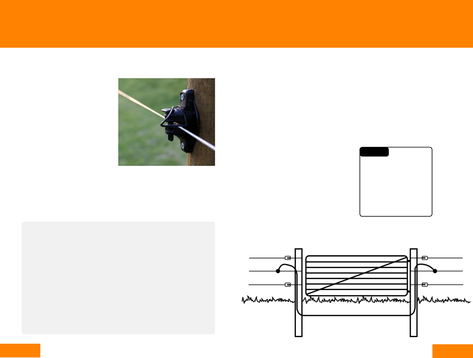
Electrified Gates
Electric gates are low cost, effective and
extremely easy to install. Choose from
high visibility electrified spring gates, ,
bungy gates and single or multi-strand
tape gates.
Electric gates should be wired so they
are dead when they are unhooked.
Tape gates provide the most visible gate
solution. Choose spring or bungy gates
where the gate needs to be stretched
across a road to divert animals into the
paddock. Gallagher Electric Gate Kits
come pre-assembled ready to install and
include an insulated gate handle.
Gates and gateways
Gallagher offers a range of insulators
for attaching electric fence wires to
your chosen post.
Wood Post Insulators
The Claw insulator provides a strong
permanent attachment system with
large shield. Alternatively Pinlock
insulator products enable the wire
to be temporarily removed from
the fence while under tension. For
example when wires need to be
lowered for temporary vehicle access.
Insulators are also available for equine
fencing products including for tape
and Equine Fence Wire. These are
all attached to the post using staples,
screws or flat head nails.
Steel Post Insulators
Gallagher manufactures quality double
pinlock insulators for attaching elec-
tric wires to steel t-posts and y-posts
as well as a topper cap for securing a
top mounted tape or wire.
Fiberglass Clips
Attach wires to Fiberglass posts using
metal clips.
Insulated Line Post Clips
Attach wires or tape to Gallagher
Insulated Line Posts using specifically
designed insulator clips.
Do not rely on electric
gates to get power across
gateways because when
the gates are open power is
lost to the fence. Also the
conductor in an electric gate
is not designed to carry high
currents so power will drop
even when closed.
CAUTION
Steel Gate example

33
32
i
Offset Fencing
Selecting Your Offsets
Offset electric fencing is an economical and easy to install option if you have an existing
or new non-electric fence that you want to protect.
Offset brackets are fitted to
a conventional fence with an
electrified wire (or wires) on one or
both sides of the fence. The wire
discourages animals from rubbing
or pushing against the fence,
thereby extending its life.
A variety of offset brackets are
available to attach to wood post or
t-post fences, or to mount directly
onto the wires of an existing non-
electric fence (barbed wire, chain
link, etc.).
Once you’ve chosen your
products, see below for the
recommended offset electric
fence set up for cattle, sheep,
pigs, goats and horses.
2.
Offset wire mounts provide
added protection for traditional
fences. This protects your fence
investment and extends the life
of the fence.
A side mount pigtail offset
is a popular option for wood
post fences. Provides
complete freedom for the
offset wire placement.
Offsets come in many options
including Porcelain. Porcelain
insulators will not break down
due to sun damage and are
resistant to fire.
Offset Fencing
Cattle
Pigs, Sheep, Goats Horses
Fence Set Up
23-46’
28-35”
20”
40”
23-46’
23-46’
Choosing offset brackets
Conventional fences can be made to last
for many more years by attaching offset
insulators with an electrified wire on one
or both sides of the fence.
Gallagher recommends attaching a single
offset wire at two thirds the height of
the animal to be controlled. If sheep and
cattle are in the same area it is better to
use two offset wires (one for sheep, one
for cows). However a single wire three
quarters the height of the sheep will still
protect the fence from both animal types.
If the old fence is tangled or has broken
wires, it will need to be repaired.
Otherwise you will run the risk of loose
non-electric wires causing accidental
shorting on the electric offset wire.
Change the worst wires and tighten the
others where possible.
Wire mount offsets twists onto your
conventional fence wire and provides
maximum flexibility when something
impacts against the fence
Chain link offsets, like wire mount
offsets, are made from galvanized high
tensile spring wire and are twisted onto
existing chain link wires.
Wood post offsets are driven into the
side or top of wood posts and then
stapled in place. The are ideal for horse
fencing due to their high visibility and
ability to mount to post and rail fencing
T-post offsets are a low cost, simple to
install offset option. They extend 5” and
their extra locking tab will fit all t-posts.
Mistakes made with an offset fence
The most common error is the use of soft
wire for the fence wire and for the offset
bracket. High tensile wire should always
be used for the fence wire, and only
spring steel wire for the offset brackets.
The bracket must be able to spring back
in place after impact or it will become
entangled with the wire of the old fence
and short out.
The second most common mistake is
the use of brackets that are too short
allowing the hot wire to remain too close
to the fence it’s attached to. Brackets
should hold the hot wire 5-12” from the
old fence. Some brackets on the market
are 4” long or less.
The placement/height of the hot wire is
also very important. It should be attached
at two-thirds the height of the animal to
be controlled. Two offset wires, can and
often are placed on the same fence. On
one side a wire is placed at 30” to contain
cattle, on the other side a wire is placed
at 8” to repel predators.
As simple as it is, offset fencing still must
be viewed as a system. One short cut, or
one substandard component can destroy
the effectiveness of the fence.

35
34
i
Temporary & Portable Fencing
Wire Selection
23-33’
28-35”
A temporary/portable electric
fence can be powered by any
Gallagher Solar or Battery
Energizer or can be simply
connected to a permanent
electric fence supplied by a
110v powered Energizer.
As portable fencing is so easy to
move and set up it’s a versatile
solution for fencing any type of
animal, even on the most remote
area of your property.
See below for the basics you’ll
need for portable fencing and
the recommended fence set up
for cattle, sheep, pigs, goats
and horses.
The Smart Fence 2, is an all-in-
one portable fence. This instant
fence system combines posts,
reels and wire in one easily
transportable package.
Ring Top Posts are a popular
choice for cattle farmers.
A single electrified wire is
sufficient to contain even the
most temperamental animals.
The multiple lugs on Multi-wire
Treadins allow attachment of
a number of wires at different
heights to accommodate a
variety of animal types.
*Note: Wire spacing will differ depending on the type of post used.
Reels hold the tape, braid or wire for the portable
fence. You can use just one reel for single line
fences or up to three reels, attached to a reel stand,
for multi-wire fences.
Tapes, Wires and Braids are used on portable fences rather than the
galvanized wire used on permanent fences. Gallagher conductors are
ideal for portable electric fences as they are light, visible and easy to wind.
Highly conductive Turbo products are ideal for fences longer than 660’
Power Connectors
are leads that connect
a portable fence to an
existing permanent
electric fence.
Posts are lightweight yet sturdy. Pigtail and Ring
Top posts are most popular for cattle fences.
Multi-wire treadins are used for all other animals.
Fence Set Up
Pigs, Sheep, Goats, Calves*
Cattle (no calves)
Horses
23-33’
8”
10”
8”
23-33’
24”
24”
Temporary & Portable Fencing
3.
* recommended for horses
Turbo Braid - 3/16”
G62174 656’, White
G62176 1,312’, White
• 9 Mixed metal strands
• Most user-friendly for horse
fencing - visible and safe
• Best suited for any distance temp
or permanent fence
8kV 7.5kV 7.1kV 125 •
Turbo Braid - 7/64”
G62148 1,312’,
White /Blue
• 9 Mixed metal strands
• Superior heavy duty strength
8kV 7.5kV 7.1kV 125 •
Turbo Wire
G62054 656’
G620564 1,312’
G62089 2,624’
• 9 Mixed metals
• Best suited to distances more
than 1/4 mile, where extreme
power is required
• 40 times more conductive than
standard Poly Wire
8kV 7.5kV 7.1kV 130 •
Poly Wire
G62004 656’
G620300 1,640’
• 6 Stainless steel strands
• Best suited for distances under
1/4 mile
5kV 2kV 1kV 6,000
/2” Turbo Tape
G62354 656’
G62356 1,312’
• Mixed metals 30x’s more
conductive
• Best suited for distances greater
than 1/4 mile
7.8kV 7.1kV 6.4kV 250 •
/2” Poly Tape
G62304 656’
• 6 Stainless steel strands for good
conductivity
4.3kV 1.5kV 0.8kV 8,500
/2” Turbo Tape *
G624544 656’
• 15 mixed strands for ultra high
conductivity
• Reinforced edges for longer
life & open weave for low wind
resistance
7.8kV 7.1kV 6.4kV 250 •
/2” Poly Tape *
G624044 656’
• 15 Stainless steel strands
• Ideal for portable electric fences
4.3kV 1.5kV 0.8kV 8,500
Braid, Wire, Rope
1/2” Tape1 1/2” Tape
Conductor
Selection Chart
MIXED
METALS*
’
FENCE
RESISTANCE
(Ohms/miles)
1.640’
FENCE
3,280’
FENCE
FENCE VOLTAGE
Wire
Preferable where wind
and adverse weather
conditions exist.
Braid
Braided construction is
designed not to tangle or
overstretch adding durability.
Tape
Generally used where
visibility is most
important.

37
36
Feral/Wildlife Fencing put this next to/
near a wildlife setup
i
Temporary & Portable Fencing
Wire Selection
Temporary & Portable Fencing
Difference between Turbo and Poly Products
There are a number of different types of
portable electric fence wires, tapes and
braids - frequently called “conductors”.
Knowing which one to choose can be a
bit tricky - especially for those new to
electric fencing.
The most common portable/temporary
fence “conductor” is what is called Poly
Wire. Poly Wire is made of plastic strands
and embedded thin metal wires used
to carry electrical current from a Fence
Charger/Energizer. The individual strands
of plastic and wire are typically twisted
tightly together to form a single wire.
A second option is Poly Tape. Poly Tape
threads individual strands of plastic and
wire together creating what appears to
be a highly visible ribbon. Tape while
prone to wind and ice damage, is the
most visible “conductor” and is best used
in situations where maximum visibility
is needed. Poly Tape comes in different
widths, but the most common are 1/2”
and 1 1/2”.
A third option is Poly Braid. Poly Braid is
thicker and more visible than Poly Wire,
and is less likely to be damaged by the
wind and ice than Poly Tape.
Poly Braid consists of individual strands
of plastic and wire that are braided
together to form a tight weave making it
more durable, and less prone to tangles
and overstretching. Poly Braid comes in
a number of different diameters (thick-
ness).
Understanding Wire
Turbo products are always
the best choice for distances
beyond 1/8 mile where
dependable power is
required.
Electrical Connections
It is important to have good
conductivity through the connection
when you join wire or tape.
To do this, separate the metal strands
by melting a strip of plastic threads
with a match or lighter approximately
2” from the ends of each length. Pull
the end off the plastic being careful
not to break the steel wires. Tie both
ends of the wire/tape together and
then twist the steel wires together.
To join 1 ½” Tape use a Tape Joiner.
These also give good electrical
contact.
Turbo products come in the same wire, tape and
braided construction previously described for Poly
- with one major difference. Turbo products have
9 strands of conductive metals including copper
which make them up to 48X’s more conductive than
Poly products which only have 6 strands of stainless
steel. This means with Turbo, your voltage will stay
strong and carry a “shock” further down your fence
line than Poly products. Long temporary fences (over
1/8 mile) should always be constructed from Turbo
products to ensure maximum livestock control.
So what is Turbo Wire
and how is it different
from Poly Wire?
Some metals conduct power better than others.
Metals that are good conductors are said to have
low resistance and metals which are not good con-
ductors have high resistance. Copper happens to be
a very low resistance conductor which enables Turbo
products to carry power further down the fence line
than Poly products. The copper wires in Gallagher’s
Turbo products are tin coated. This is why if you
pull the plastic and metal strands apart, you will not
see copper colored wires. The advantages of tinned
copper over a non-tinned copper wire is greater
longevity. Copper coated in tin is less susceptible to
corrosion and even more conductive!
Why is copper so
important?
What this means is that if you built two different
fences .6 miles long and one was a single strand of
Poly Wire and the other was a single strand of Turbo
Wire - both fences would read 8,000 volts at the
start; however, at the end of the fence you would
only read 600 volts on the Poly Wire fence while the
Turbo Wire fence would read 6,300 volts.
The resistance of a “conductor” (wire/tape/braid) is
measured in Ohms. The lower the resistance, the
more conductive the wire/tape/braid will be. As you
can see from the values below, Turbo Braid is 48
times more conductive than Poly Wire.
Turbo Braid - 125 Ohms/mile
Poly Wire - 6000 Ohms/mile
What does it mean
that “Turbo is 48X’s
more conductive than
Poly”?

39
38
ELECTRIC FENCE SYSTEM D Portable/Temporary Fencing
i
Temporary & Portable Fencing
Fence Posts
Temporary & Portable Fencing
Reel and Gate Selection
Reels
Reels are an absolutely essential
component of your portable electric
fencing equipment.
They are designed to hold your wire, braid
or tape and make it extremely quick and
easy to roll up your temporary
cross-fences.
Gallagher’s geared reel comes with a
locking device allowing for secure
attachment to an ATV or fence wire.
Geared reels also have a 3:1 ratio which
means for each turn of the handle, the
bobbin spins three times allowing you to
wind your wire three times faster with
each turn of the handle.
Geared reels are designed to hook the
spool in place so it does not unravel.
The hook allows you to hang the reel off
of your permanent high-tensile electric
fence.
An alligator clamp (also called a lead con-
nector) is used to create a good electrical
connection between the portable electric
fence and your permanent electric fence.
Use an insulated handle on the far end
of your portable electric fence so the
fence is only powered from one side (at
the geared reel). This ensures that the
portable fence loses power once you
disconnect the alligator clamps and
geared reel so you can roll up the wire
without getting shocked.
When rewinding long lengths of poly/
turbo wire, braid and tape, the geared
reel is a worthwhile, time-saving
investment.
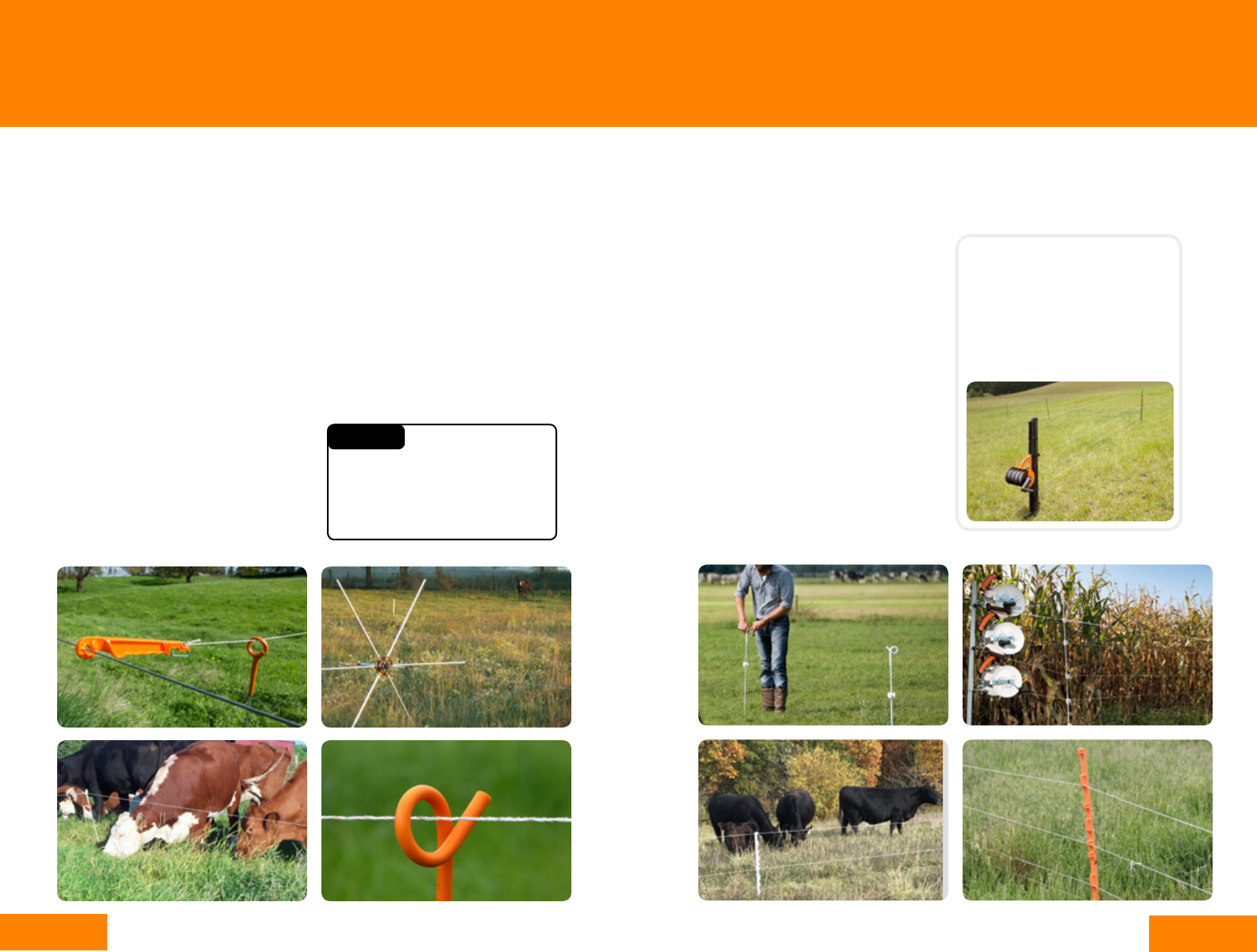
Portable Fence Posts
When installing a temporary fence, there
are many durable, portable fence post
options available.
Many portable fence posts come with a
step-in feature. At the base of a step-in
post, there is a footplate that allows you
to push the post into the ground with your
foot. This is a convenient feature so you
won’t need to drop your bundle of posts in
order to pound them into the ground.
Other factors to consider are visibility,
durability and the ability to add
multiple wires for the animal needing to
be fenced. Weather also influences
selection as posts are much more
difficult to insert into frozen ground.
Plastic Posts
Plastic step-in posts with built-in foot
plates are convenient because they have
pre-molded loops for multiple wires at
various heights. Plastic posts are made
from a heavy duty, UV-resistant polymer
plastic and have a steel foot spike.
Metal Posts
Metal step-in pigtail posts are also
available. These posts get their name
from the curl loop that holds the wire and
looks similar to a pig’s tail.
Gallagher’s Ring Top Posts have a very
high strength plastic head and foot
coming in both a standard and heavy duty
model.
Gallagher’s Ring Top Post while similar to
the Pigtail, has a ring shaped nylon head
that prevents wear and reduces tangles.
The post’s glass reinforced nylon
footplate is strong and will not bend.
A Multi-Wire Ring Top Post is also
available. This product is suitable for
containing most animals including cattle,
sheep and goats.
Fiberglass Posts
Fiberglass rods are better for
situations when the fence is not going to
be moved as often because these have to
be pounded into the ground. These rods
require the use of wire clips or plastic
insulators that slide on the rod to hold the
wire in place.
Rolling Posts
The Tumblewheel enables you to quickly
and easily roll a fence line to a new
position. The Tumblewheel’s unique
center hub maintains power while the
fence is being moved. It can be used on
flat very hard and frozen ground. The legs
remain live except for two legs that are
on the ground.
Where several breaks are needed in one
paddock, Tumblewheels are ideal for
quick and efficient rationing of grass. We
recommend spacing at every 66’.
This fence consists of a number of
electrified ‘wheels’ spaced across the
pasture. The wheels are held upright with
the tension of the single line fence which
passes through the center.
When one or both ends of the fence is
moved, the wheels roll along. When you
stop, the fence stops.
41
40
Multi-wire Fence
1. Attach the required reels to a reel
stand & chain the reel stand to an
anchor point.
2. Hook the insulated handles through
the head/lug of the first post to
prevent them becoming twisted.
3. Follow steps 2-6 as per the single
wire fence instructions only this time
with multiple lines together not one
single one.
Note – place posts every 33-40’ and
use a multi-reel lead connector if
using a battery Energizer.
Portable Fence Construction
Reels holding wire/tape can be used individually for single line fences or for up to
three lines using three reels attached to a reel stand.
Single Wire Fence:
1. Hook the reel to the anchor point
(e.g.: permanent fence/reel stand) and
disengage the ratchet.
2. Carrying the insulated handle and
sufficient portable posts, walk along
the proposed line allowing the reel to
unwind and connect to the other end.
3. Walk back to the reel, placing a post
every 50’ (or closer on uneven ground)
and locate the wire/tape in the post.
4. At the end of the fence, engage the
ratchet and tension the wire.
5. Connect to power – either connect to
the permanent fence by connecting
leadset to both powered permanent
fence line and the portable wire or
using a solar or battery Energizer.
6. When you remove the fence, do the
same process in reverse.
ELECTRIC FENCE SYSTEM D Portable/Temporary Fencing
i
Temporary & Portable Fencing
Single Wire Construction
Temporary & Portable Fencing
Multi-Wire Construction
All in one multi-wire portable
fence system
A quicker and easier all in
one instant fence system, the
Smart Fence System includes
4 wires, 10 posts, 328’ length.
Energizer is sold separately.
Do not wind the conductor through
the posts as the abrasion will
damage the post.
CAUTION

43
42
ELECTRIC FENCE SYSTEM D Portable/Temporary Fencing
i
Fault Finding
Searching for a fault
A short is a fault somewhere on the
fence that has caused it to lose power.
The most common types are
vegetation overgrowth, loose wires
and broken insulators.
Gallagher has some great tools for testing
and finding these quickly and easily.
• Fault Finder – shows voltage, current and
direction of fault (an i Series Remote also
has this function)
• Fence Volt Meter - a digital read out of
the voltage at that point on the fence
• Live Fence Indicator – sits on your fence
line and flashes with each pulse over 2kV
so you can see from a distance
To trace a fault using a volt meter travel
along the fence line and check the voltage
about every 330’ . If the short is serious,
the voltage will continue to fall until the
fault is reached. If the fault is passed the
voltage will remain fairly constant. You
should then backtrack to find it. At fence
junctions isolate different fences with a
Cut Out Switch to try to isolate the fault.
Using a Fault Finder
1. Place the Fault Finder or remote on the
fence with the wire in the measurement
slot and making good contact with the
contact plate.
2. The arrow on the LCD display will
indicate which direction the current is
flowing. The amount of current (Amps)
and voltage (kV) will show on the display.
The higher the current, the bigger the
fault.
Travel along the fence line checking the
readings every 330’ or so. If the current
reading drops significantly the fault is
back towards your previous reading. The
process is similar to finding water leaks,
where the Fault Finder is reporting the
amount and direction of the flow.
Multi Wire Fences
When the fence has multiple live wires,
the current should be measured on
each wire. Assuming the live wires are
connected in parallel at each end of the
fence the total current flow is the sum of
the current on each wire.
When one wire has a much higher current
reading than the others, either this wire
has the fault on it or the wires have not
been connected in parallel at each end
of the fence line and this wire only is
supplying power to the next section of
fence.
Induction
Induction is the transfer of voltage
from a live wire to a neutral wire by
electromagnetic rather than direct physical
contact.
If you are getting a small shock from
“non-live” wires or steel gates, particular
in dry weather, this is likely to be caused
by induction. Neutral wires (neither live
nor ground) can be charged from live wires
(usually leadout or offset wires), running in
parallel. It is not a short and will not reduce
fence voltage.
To remove the problem, ground out the
offending wires by pushing a heavy gauge
galvanized wire as far as possible into the
ground next to the strain post and staple
it across the offending wires. This will
not reduce the voltage on the insulated
powered wires.
If you find there is not enough power on your fence follow the chart below to find the
most common causes.
Fault Finding
Faulty ground system
Install the grounding
system.

45
44
General safety
Don’t touch fences with your head or mouth.
People with pacemakers or other heart
problems also should consult their doctors
before working with or near electric fences.
Always use precautions.
Energizer installation
Only connect one energizer to a fence.
Can electric fences cause fires?
There is a misconception that dry
vegetation touching an electric fence can
cause fires – this is extremely unlikely. In
order to create a short, vegetation needs
to be damp or green so therefore the
vegetation will not ignite. Once vegetation
dries out it becomes non-conductive
meaning any short created disappears.
The only conceivable but still very unlikely
scenario where an electric fence could
start a fire is when a wire shorts to an
grounded metal object, such as a steel post
or wire where insulators have broken, in the
presence of abundant dry vegetation. This
scenario is very unlikely to occur in practice,
and even less so on a well-maintained
fence.
Producers with fences on steel posts or
those using grounded wires in the fence
are advised to ensure the live wires are
well insulated and the fence is clear of
vegetation. If these factors are of concern
then on days of severe or above fire risk,
consider turning the energizer off.
Ground rods for energizers should be at
least 65’ from utility grounding fields.
Electric fence construction
Avoid running fences parallel to power lines,
and try to install fences so that they cross
power lines at right angles. If you can’t avoid
parallel electric fences and power lines,
offset the fences at least 30 feet from the
power lines, and make sure the top fence
wires are no more than six feet high.
Do not attach fence wires to utility poles.
Electric fences bordering public
thoroughfares are required to have a
warning sign at least every 295’ feet where
the public has access to electric fences,
such as along roads.
Check with your local authority for
specific regulations.
Landowners are responsible for preventing
audible interference with telephone lines.
Therefore, try to avoid installing electric
fences under telephone wires, and minimize
the distance that electric fence wires run
parallel to underground telephone cables.
This particularly applies if the electric fence
wire is carrying high current, such as a
leadout wire to a large fencing system. (See
‘Telephone Interference’ pg 46)
ELECTRIC FENCE SYSTEM D Portable/Temporary Fencing
i
Safety
Safety
Never use barbed wire for electric fence wire
because people or animals could more easily
become entangled in it.
Radio Interference
Keep electric fences as far away from radio
antennas as possible. Gallagher energizers
comply with usual Telecom and International
standards and safety regulations. However,
problems can arise for a number of reasons
and can be difficult to eliminate in areas with
poor radio reception.
To avoid radio interference:
• The energizer ground must be highly
conductive
• The energizer must be well away from
any electrical power supply
• The energizer should be well away from
any water pipes
Do not allow an energizer ground wire to
touch a building which can act as a broadcast
aerial. Use proper leadout cable to insulate
the ground wire. Ground the offending radio
and improve its aerial. Try to keep both as far
away from the energizer and fence lines as
possible.
Here are some safety considerations to follow when installing electric fencing:
All types of wire
may break and
recoil when
stretched. Always
use hand and eye
protection when
handling hi-tensile
wire.

47
46
Are all sections of the fence and the
connecting leads over 10 metres away
from the telephone cables or lines?
Is the ground system inadequate or
within 10 metres of a power or
telecommunications ground or
building structure with mains power?
Y - Improve or relocate the ground.
connecting leads within 10 metres of the
Telephone Interference
Use the following chart flow to determine if your fence is likely to be causing interference
on telephone lines.
i
Safety
Safety
1. Draw a plan of the property approximately to scale showing:
• All electrified wires.
• The connecting leads between Energizer, fence and ground rods.
• Wires crossing gateways and roads (including underground)
• Communication cables/lines
• A 640’ wide shaded stripe centred on each side of the communication cables/lines
2. Highlight any electric fence wires
• Within the shaded area
• That run parallel to communication cables/lines and are within 330’ of them (running
at right angles is OK and shouldn’t cause a problem)
330’
330’
Designing electric fences to prevent interference
Telephone cable

49
48
i
Safety
Safety
What Not to Do – an interference heavy layout
1. Highly conductive lead out line runs down the driveway/road,
adjacent to communication cables/lines
2. Ground rods are connected in parallel to communications cables/
lines
3. Highly conductive lead out line is less than 330’ from and not at right
angles to, communication cables/lines when it crosses the road
What To Do – a clean fence
1. Energizers and lead out are at least 330’ away from
communication cables/lines.
2. Sections of the fence that are less than 330’ away are as short
as possible and left open-circuited at the far end (i.e. nothing
connected to the far end).
3. Electric fence ground is separate from all other grounding
systems, is as short as possible, and is routed away from
communication cables/lines.
495’
495’

51
50
#1 Energizer is not on or there is no
volt meter reading across the energizer
output terminals with the energizer
disconnected from the fence.
Potential Causes:
1) Mainline power outage or blown fuse on
input circuit
Solution: Restore power or replace blown
fuse
2) Energizer is switched off or in Standby
mode
Solution: Check energizer “on-off” switch.
3) Dry cell batteries are dead; wet cell
batteries are discharged
Solution: Recharge or replace batteries
4) Battery terminals are corroded
Solution: Clean terminals
5) Energizer is faulty
Solution: Have energizer serviced
#2 Energizer is on, but volt meter
reading is low across the energizer
output terminals when disconnected
from fence.
Potential Causes:
1) Weak batteries
Solution: Recharge or replace batteries
2) Battery terminals are corroded
Solution: Clean battery terminals
Troubleshooting
3. Energizer is faulty
Solution: Send for repair
#3 Energizer is operating, but there is
no volt meter reading on the fence with
the energizer connected to fence and
ground
Potential Causes:
1) Ground-return or fence lead-out wire is
disconnected or broken
Solution: Connect or repair fence or
ground-return wire
2) Broken, corroded or disconnected live
wire or ground-return on fence
Solution: Connect or repair live wire or
ground-return on fence
3) Soil is dried out
Solution: Install ground-return wire
#4 Low volt meter readings at several
locations on fence
Potential Causes:
1) Energizer is on low setting or is
inadequate for length of fence
Solution: Switch energizer to high setting;
install more powerful Energizer
2) Weak batteries
Solution: Recharge or replace batteries
3) Terminals corroded
Solution: Clean terminals
4) Ground system is inadequate or
deteriorated
Solution: Repair or replace ground system
5) Soil is dried out
Solution: Install ground-return wire
6) The fence has faults
Solution: Repair fence faults
ELECTRIC FENCE SYSTEM D Portable/Temporary Fencing
i
Troubleshooting
Common electric fencing issues & solutions
Troubleshooting
#5 No volt meter readings at several
locations on fence
Potential Causes:
1) Broken or disconnected fence
wire, underground cable or ground wire
Solution: Connect or repair wire; remove
cause of short; replace jumper connection
2) Ground rod connection deteriorated
Solution: Replace ground rod connection
3) A Cut Out Switch has been left open
Solution: Close Cut Out Switch
#6 Volt meter reading on one wire is
higher than on another wire, or there
is no reading from one live wire to
ground-return or soil
Potential Causes:
1) Broken or disconnected fence
wire, connecting wire or ground wire
Solution: Connect or repair wire; remove
cause of short; replace jumper connection
2) Broken or faulty insulators
Solution: Replace faulty insulators
3) Ground connection rod deteriorated
Solution: Replace ground connection rod
#7 Radio, TV or telephone interference
Potential Causes:
1) Ground system inadequate
Solution: Increase grounding capacity
2) Antenna too close to fence
Solution: Relocate antenna or telephone
wires
3) Fence is parallel with antenna
wires or telephone lines
Solution: De-electrify or relocate segment
of fence that is parallel to or too close to
antenna or wires

52
TEL: 800 531 5908
FAX: 800 444 5422
EMAIL in[email protected].com
www.GallagherUSA.com
www.Gallagher.ca
GALLAGHER NORTH AMERICA
5005 NW 41st Street
Riverside, MO 64150
V
